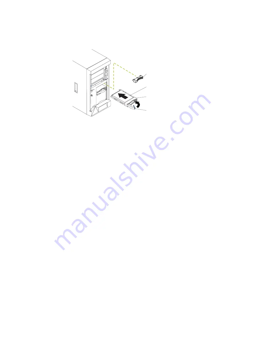
Installing a hot-swap hard disk drive
The following illustration shows how to install a hot-swap hard disk drive.
Slim
filler panel
Hard disk drive
Drive tray
Drive tray handle
(in open position)
Complete the following steps to install a drive in a hot-swap bay.
Attention:
To maintain proper system cooling, do not operate the server for more
than 10 minutes without either a drive or a filler panel installed for each bay.
Note:
All hot-swap drives being used in the server should have the same
throughput speed rating; mixing speed ratings might cause all drives to
operate at the lower throughput speed.
1. Review the information in “Installation guidelines” on page 41, “Handling
static-sensitive devices” on page 42, and “Safety information” on page 163.
2. Remove the filler panel from one of the empty hot-swap bays.
3. Install the hard disk drive in the hot-swap bay:
a. Ensure that the tray handle is open (that is, perpendicular to the drive).
b. Align the drive assembly with the guide rails in the bay.
c. Gently push the drive assembly into the bay until the drive stops.
d. Push the tray handle to the closed (locked) position.
e. Check the hard disk drive status indicator to verify that the hard disk drive is
operating properly.
If the amber hard disk drive status LED for a drive is lit continuously, that
drive is faulty and needs to be replaced. If the green hard disk drive activity
LED is flashing, the drive is being accessed.
Note:
If your server is configured for RAID operation using the integrated SCSI
controller with RAID capabilities or an optional ServeRAID controller, you
might need to reconfigure your disk arrays after installing hard disk
drives. See the ServeRAID documentation on the
IBM ServeRAID
Support
CD for additional information on RAID operation and complete
instructions for using ServeRAID Manager.
74
xSeries 235 Type 8671: Hardware Maintenance Manual and Troubleshooting Guide
Содержание eServer xSeries 235 Type 8671
Страница 1: ...xSeries 235 Type 8671 Hardware Maintenance Manual and Troubleshooting Guide ERserver ...
Страница 2: ......
Страница 3: ...xSeries 235 Type 8671 Hardware Maintenance Manual and Troubleshooting Guide ERserver ...
Страница 34: ...24 xSeries 235 Type 8671 Hardware Maintenance Manual and Troubleshooting Guide ...
Страница 50: ...40 xSeries 235 Type 8671 Hardware Maintenance Manual and Troubleshooting Guide ...
Страница 134: ...124 xSeries 235 Type 8671 Hardware Maintenance Manual and Troubleshooting Guide ...
Страница 164: ...154 xSeries 235 Type 8671 Hardware Maintenance Manual and Troubleshooting Guide ...
Страница 170: ...160 xSeries 235 Type 8671 Hardware Maintenance Manual and Troubleshooting Guide ...
Страница 183: ...Appendix B Related service information 173 ...
Страница 184: ...174 xSeries 235 Type 8671 Hardware Maintenance Manual and Troubleshooting Guide ...
Страница 185: ...Appendix B Related service information 175 ...
Страница 186: ...176 xSeries 235 Type 8671 Hardware Maintenance Manual and Troubleshooting Guide ...
Страница 187: ...Appendix B Related service information 177 ...
Страница 188: ...178 xSeries 235 Type 8671 Hardware Maintenance Manual and Troubleshooting Guide ...
Страница 189: ...Appendix B Related service information 179 ...
Страница 190: ...180 xSeries 235 Type 8671 Hardware Maintenance Manual and Troubleshooting Guide ...
Страница 200: ...190 xSeries 235 Type 8671 Hardware Maintenance Manual and Troubleshooting Guide ...
Страница 201: ...Appendix B Related service information 191 ...
Страница 202: ...192 xSeries 235 Type 8671 Hardware Maintenance Manual and Troubleshooting Guide ...
Страница 206: ...196 xSeries 235 Type 8671 Hardware Maintenance Manual and Troubleshooting Guide ...
Страница 211: ...Japanese Voluntary Control Council for Interference VCCI statement Appendix C Notices 201 ...
Страница 212: ...202 xSeries 235 Type 8671 Hardware Maintenance Manual and Troubleshooting Guide ...
Страница 213: ......
Страница 214: ... Part Number 59P6524 1P P N 59P6524 ...


