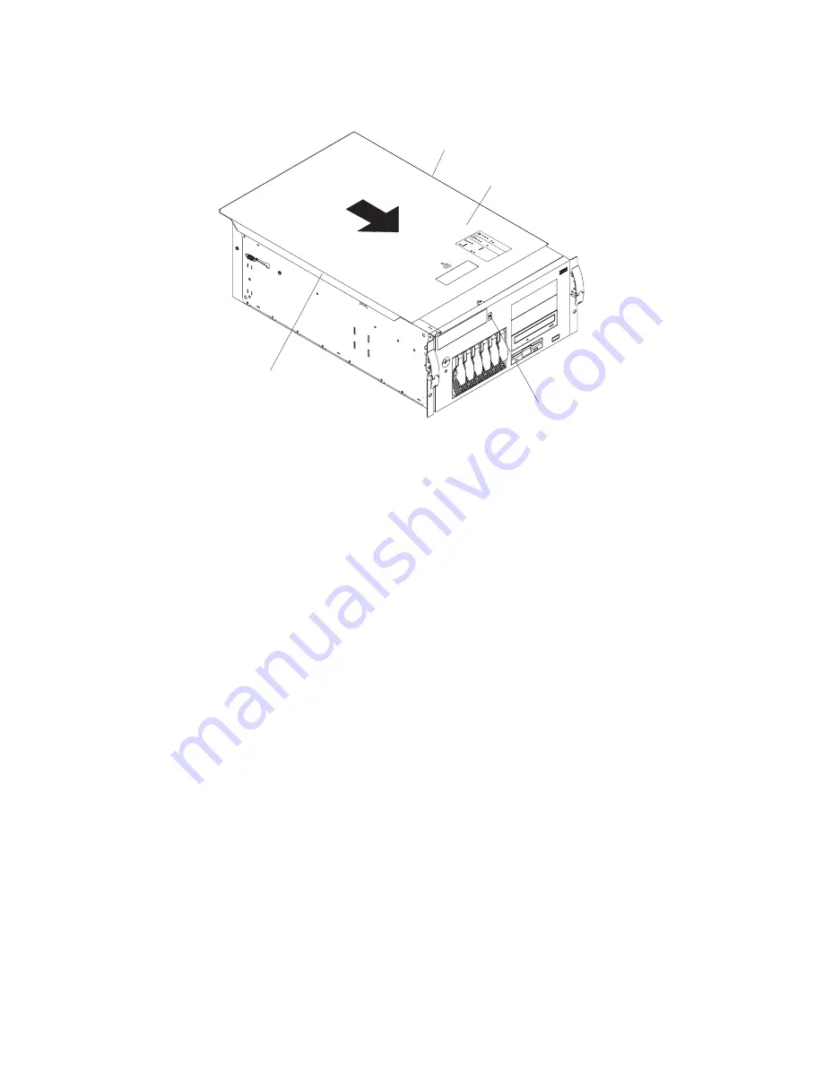
The following illustration shows how to install the server top cover on a rack
configuration server.
Top cover
Cover release
latch
CP
U
VR
M
M
EM
O
RY
H
D
D
PC
I B
U
S
N
M
I
SM
I
SER
VI
C
E
PR
O
C
ES
SO
R
BU
S
N
O
N
R
ED
U
N
DA
NT
PO
W
ER
SU
PPL
Y
1
2
3
A
B
1
2
3
FA
N
TEM
PER
AT
U
RE
Flange
Flange
Complete the following steps to install the server top cover:
1. Before installing the cover, check that all cables, adapters, and other
components are installed and seated correctly and that you have not left loose
tools or parts inside the server.
2. Place the cover-release latch in the open (up) position.
3. Place the lip of the left side of the top cover over the top-left edge of the server
chassis.
4. Rotate the top cover to a horizontal position, inserting the tabs at the right side
of the top cover into the matching slots in the server chassis.
5. Slide the top cover forward until it locks in place.
6. If you disconnected any cables from the back of the server, reconnect the
cables; then, plug the power cords into properly grounded electrical outlets.
Note:
If necessary, see “Input/output connectors” on page 104 for connector
locations. The
Rack Installation Instructions
provided on the IBM
xSeries
Documentation
CD also give additional rack installation and cabling
information.
Updating your server configuration
When you start your server for the first time after you add or remove an internal
option or an external SCSI device, you might see a message telling you that the
configuration has changed. The Configuration/Setup Utility program automatically
starts so that you can save the new configuration information (see “Starting the
Configuration/Setup Utility program” on page 12).
Some options have device drivers that you need to install. See the documentation
that comes with your option for information about installing any required device
drivers.
Your server comes with one or two microprocessors installed on the system board.
If your server comes with two microprocessors, or if your server comes with one
microprocessor and you have installed an additional microprocessor, your server
can now operate as an SMP server. Therefore, you might need to upgrade your
100
xSeries 235 Type 8671: Hardware Maintenance Manual and Troubleshooting Guide
Содержание eServer xSeries 235 Type 8671
Страница 1: ...xSeries 235 Type 8671 Hardware Maintenance Manual and Troubleshooting Guide ERserver ...
Страница 2: ......
Страница 3: ...xSeries 235 Type 8671 Hardware Maintenance Manual and Troubleshooting Guide ERserver ...
Страница 34: ...24 xSeries 235 Type 8671 Hardware Maintenance Manual and Troubleshooting Guide ...
Страница 50: ...40 xSeries 235 Type 8671 Hardware Maintenance Manual and Troubleshooting Guide ...
Страница 134: ...124 xSeries 235 Type 8671 Hardware Maintenance Manual and Troubleshooting Guide ...
Страница 164: ...154 xSeries 235 Type 8671 Hardware Maintenance Manual and Troubleshooting Guide ...
Страница 170: ...160 xSeries 235 Type 8671 Hardware Maintenance Manual and Troubleshooting Guide ...
Страница 183: ...Appendix B Related service information 173 ...
Страница 184: ...174 xSeries 235 Type 8671 Hardware Maintenance Manual and Troubleshooting Guide ...
Страница 185: ...Appendix B Related service information 175 ...
Страница 186: ...176 xSeries 235 Type 8671 Hardware Maintenance Manual and Troubleshooting Guide ...
Страница 187: ...Appendix B Related service information 177 ...
Страница 188: ...178 xSeries 235 Type 8671 Hardware Maintenance Manual and Troubleshooting Guide ...
Страница 189: ...Appendix B Related service information 179 ...
Страница 190: ...180 xSeries 235 Type 8671 Hardware Maintenance Manual and Troubleshooting Guide ...
Страница 200: ...190 xSeries 235 Type 8671 Hardware Maintenance Manual and Troubleshooting Guide ...
Страница 201: ...Appendix B Related service information 191 ...
Страница 202: ...192 xSeries 235 Type 8671 Hardware Maintenance Manual and Troubleshooting Guide ...
Страница 206: ...196 xSeries 235 Type 8671 Hardware Maintenance Manual and Troubleshooting Guide ...
Страница 211: ...Japanese Voluntary Control Council for Interference VCCI statement Appendix C Notices 201 ...
Страница 212: ...202 xSeries 235 Type 8671 Hardware Maintenance Manual and Troubleshooting Guide ...
Страница 213: ......
Страница 214: ... Part Number 59P6524 1P P N 59P6524 ...


