Before installing a drive in bays 1, 2, 3, or 4, do the following:
1. Read “Safety information” on page 117, “Handling static-sensitive devices” on
page 38, and the documentation that comes with your drive.
2. Choose the bay in which you want to install the drive.
3. Check the instructions that come with the drive to see if you need to set any
switches or jumpers on the drive. If you are installing a SCSI device, be sure to
set the SCSI ID for that device.
Power and signal cables for internal drives
Your server uses cables to connect IDE and SCSI devices to the power supply and
to the system board. The following cables are provided:
v
Four-wire power cables connect the drives to the power supply. At the end of
these cables are plastic connectors of various sizes that can be attached to
different drives.
v
Flat signal cables, also called ribbon cables, connect IDE, SCSI, and diskette
drives to the system board. Two or three sizes of ribbon cables come with your
server:
– The wider IDE signal cable has two or three connectors.
- If the cable has three connectors, one of these connectors is attached to
the drive, one is a spare, and the third is attached to the primary or
secondary IDE connector on the system board.
- If the cable has two connectors, one of these connectors is attached to the
hard disk drive, and the other is attached to the primary or secondary IDE
connector on the system board.
Note:
The CD-ROM drive is attached to an ATA 66 signal cable. The hard
disk drive is attached to an ATA 100 signal cable. ATA 66 and ATA 100
signal cables are color-coded. The blue connector attaches to the
system board. The black connector attaches to the primary device. If
the cable has a gray middle connector, it attaches to the secondary
device. If you are installing a hard disk drive, you must change the
switch setting on the CD-ROM drive to secondary and change the
connector used for the CD-ROM drive to the gray middle connector.
– The narrower signal cable has two connectors, one to attach to the diskette
drive, and the other to attach to the connector (FDD1) on the system board.
– If your server comes with a SCSI connector on the extender board and SCSI
hard disk drive, an Ultra160 twisted ribbon cable connects the internal
Ultra160 SCSI hard disk drive to the SCSI connector on the PCI extender
board. This cable has two additional connectors for attaching more internal
SCSI devices.
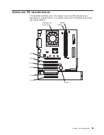
To locate connectors on the system board, see “System board internal cable
connectors” on page 36.
Review the following information before connecting power and signal cables to
internal drives:
v
The drives that are preinstalled in your server come with power and signal cables
attached. If you replace any drives, remember which cable is attached to which
drive.
v
When you install a drive, ensure that the drive connector at one end of the signal
cable is connected to the drive and that the drive connector at the other end is
connected to the system board.
Chapter 4. Installing options
49
Содержание eServer xSeries 205 Type 8480
Страница 1: ...IBM xSeries 205 Type 8480 Hardware Maintenance Manual and Troubleshooting Guide ERserver ...
Страница 2: ......
Страница 3: ...IBM xSeries 205 Type 8480 Hardware Maintenance Manual and Troubleshooting Guide ERserver ...
Страница 6: ...iv IBM xSeries 205 Type 8480 Hardware Maintenance Manual and Troubleshooting Guide ...
Страница 10: ...viii IBM xSeries 205 Type 8480 Hardware Maintenance Manual and Troubleshooting Guide ...
Страница 18: ...8 IBM xSeries 205 Type 8480 Hardware Maintenance Manual and Troubleshooting Guide ...
Страница 30: ...20 IBM xSeries 205 Type 8480 Hardware Maintenance Manual and Troubleshooting Guide ...
Страница 76: ...66 IBM xSeries 205 Type 8480 Hardware Maintenance Manual and Troubleshooting Guide ...
Страница 94: ...84 IBM xSeries 205 Type 8480 Hardware Maintenance Manual and Troubleshooting Guide ...
Страница 118: ...108 IBM xSeries 205 Type 8480 Hardware Maintenance Manual and Troubleshooting Guide ...
Страница 124: ...114 IBM xSeries 205 Type 8480 Hardware Maintenance Manual and Troubleshooting Guide ...
Страница 137: ...Appendix B Related service information 127 ...
Страница 138: ...128 IBM xSeries 205 Type 8480 Hardware Maintenance Manual and Troubleshooting Guide ...
Страница 139: ...Appendix B Related service information 129 ...
Страница 140: ...130 IBM xSeries 205 Type 8480 Hardware Maintenance Manual and Troubleshooting Guide ...
Страница 141: ...Appendix B Related service information 131 ...
Страница 142: ...132 IBM xSeries 205 Type 8480 Hardware Maintenance Manual and Troubleshooting Guide ...
Страница 143: ...Appendix B Related service information 133 ...
Страница 144: ...134 IBM xSeries 205 Type 8480 Hardware Maintenance Manual and Troubleshooting Guide ...
Страница 154: ... 144 IBM xSeries 205 Type 8480 Hardware Maintenance Manual and Troubleshooting Guide ...
Страница 155: ...Appendix B Related service information 145 ...
Страница 156: ...146 IBM xSeries 205 Type 8480 Hardware Maintenance Manual and Troubleshooting Guide ...
Страница 160: ...150 IBM xSeries 205 Type 8480 Hardware Maintenance Manual and Troubleshooting Guide ...
Страница 166: ...156 IBM xSeries 205 Type 8480 Hardware Maintenance Manual and Troubleshooting Guide ...
Страница 167: ......
Страница 168: ... Part Number 59P2108 1P P N 59P2108 ...

