Position
Step
1 (UIO Network)
2 (UIO Slot1)
3, 4, 5 (PLX Slot1, WIO Slot1, WIO Slot2)
3.
If you are working with a PCIe adapter in position 2, do the following:
a.
Remove the standard tailstock from the adapter.
b.
If you are inserting a storage drive adapter, connect the signal cables to the adapter before
inserting the adapter. See “Drive installation details for the 8001-12C system” on page 87 for
cabling information.
c.
If needed, install a support bracket for the PCIe adapter to the system backplane. Also install a
special support tailstock to the PCIe adapter.
d.
Insert the adapter into the PCIe riser.
e.
If you installed the support bracket for the PCIe adapter, fasten the special support tailstock to
that bracket.
4.
If you are working with the PCIe adapter in position 1, do the following steps:
a.
Replace the PCIe adapter riser into the system backplane.
b.
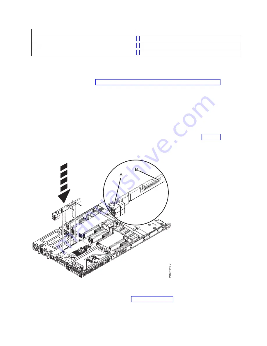
Replace the two screws to secure the PCIe riser card to the chassis as shown in Figure 40.
c.
If a PCIe adapter was in position 2, replace that adapter.
5.
If you need to replace the riser cards for positions 3 (A), or 4 or 5 (B); replace the screws that secure
the PCIe riser card to the cage (C) as shown in Figure 41 on page 38.
Figure 40. Replacing the PCIe riser screws
Removing and replacing parts
37
Содержание CS821
Страница 1: ...Power Systems Servicing the IBM Power System S821LC 8001 12C or the IBM CS821 8005 12N IBM ...
Страница 2: ......
Страница 3: ...Power Systems Servicing the IBM Power System S821LC 8001 12C or the IBM CS821 8005 12N IBM ...
Страница 16: ...xiv Power Systems Servicing the IBM Power System S821LC 8001 12C or the IBM CS821 8005 12N ...
Страница 116: ...100 Power Systems Servicing the IBM Power System S821LC 8001 12C or the IBM CS821 8005 12N ...
Страница 117: ......
Страница 118: ...IBM Printed in USA ...


