background image

Chapter 4  Audio Driver Installation Guide 

70 

CI5VGM User’s Manual 


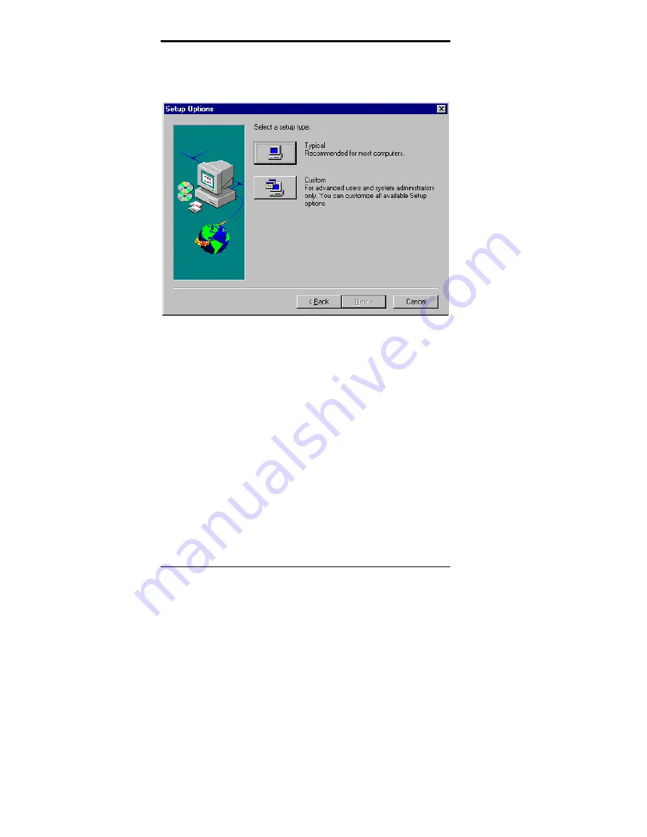
Step 9. When the figure below appears, click 

Typical

, and then continue 

the installation by following Install Wizard. It is recommended 
that the default settings assigned by the Install Wizard be applied 
during the first time installation. 


Содержание CI5VGM Series

Страница 1: ...CI5VGM Series Full Size Pentium All in one CPU Card Version 1 0A Industrial CPU Card PC Based Computer Boards for Industrial Automation User s Manual...

Страница 2: ...t special exemplary incidental incidental or consequential damages resulting from any defect or omission in this manual even if advised of possibility of such damages The material contained herein is...

Страница 3: ...Installation 12 Jumpers on the CI5VGM 14 Connectors on the CI5VGM 24 Watchdog Timer Configuration 37 Chapter 3 BIOS Configuration 38 Chapter 4 Audio Driver Installation Guide 65 Chapter 5 VGA Driver I...

Страница 4: ......

Страница 5: ...el ON ON ON OFF 640x480 16 OFF ON ON OFF 800x600 16 ON OFF ON OFF 1024x768 16 OFF OFF ON OFF 1024x768 24 ON ON OFF OFF 1280x1024 24 Settings for New Cyrix AMD CPUs on off off on off off off off 95MHz...

Страница 6: ...formation on the CI5VGM CPU card It is divided into the following sections Checklist 3 Description 3 Features 4 Specifications 4 Intelligence 7 Board Dimensions 8 The topics covered in this chapter ar...

Страница 7: ...2558B LAN Driver 5 Diskettes Containing YAMAHA 715 Audio Driver 1 Diskette Containing System Monitor Utility 1 Optional CD containing Intel LANDesk Client Manager Description The CI5VGM is a Pentium I...

Страница 8: ...itoring Win95 shut off Modem ring on via ATX power 10 100M Base T Ethernet interface IEEE 802 3 compliance specification Port 80 display LED COM2 supports RS232 433 485 Specifications Processor Socket...

Страница 9: ...ort SPP EPP ECP mode Serial Port Two 16550 UART compatible ports with COM1 as RS232 and COM2 jumper configurable as RS232 422 485 Enhanced IDE Two Bus Mastering EIDE mode up to 4 devices Two EIDE inte...

Страница 10: ...0 2 4 6 8 10 12 14 16 18 20 22 24 26 28 30 seconds 20 PCI Bus Ethernet Interface Intel 82558B PCI local bus Ethernet controller IEEE802 3u auto negotiation for automatic speed selection 10 100Mbps ope...

Страница 11: ...e exceeds the safe heat level Windows 95 shut off Allows shut off control from within Windows 95 and through an ATX power supply Modem ring on Allows system powering on through an external modem and t...

Страница 12: ...Chapter 1 Introduction 8 CI5VGM User s Manual Board Dimensions...

Страница 13: ...Chapter 1 Introduction CI5VGM User s Manual 9 This page is intentionally left blank...

Страница 14: ...hapter provides information on how to use the jumpers and connectors on the CI5VGM in order to set up a workable system The topics covered are CPU Installation 11 Memory Installation 12 Jumpers on the...

Страница 15: ...h a lever to secure the processor Make sure the notch on the corner of the CPU corresponds with the notch on the inside of the socket After you have installed the processor into the ZIF socket check i...

Страница 16: ...lowing table on how to configure the memory NOTE You must install memory modules of the same type either all SDRAM or all EDO DRAM 168Pin DIMM 3 3V SDRAM or EDO DRAM DIMM3 DIMM2 DIMM1 Total Memory 8MB...

Страница 17: ...MB 128MB 32MB 160MB 32MB 32MB 8MB 72MB 64MB 32MB 8MB 104MB 128MB 32MB 8MB 168MB 32MB 32MB 16MB 80MB 64MB 32MB 16MB 112MB 128MB 32MB 16MB 176MB 32MB 32MB 32MB 96MB 64MB 32MB 32MB 128MB 128MB 32MB 32MB...

Страница 18: ...ntact your dealer or sales representative The following table lists the connectors on CI5VGM and their respective functions Jumper Locations on the CI5VGM 15 SW1 1 8 CPU Frequency Selector 16 JP2 SDRA...

Страница 19: ...Chapter 2 Installations CI5VGM User s Manual 15 Jumper Locations on the CI5VGM...

Страница 20: ...on 60MHz 60MHz 2x P54C 120 off on on off on off off on 66MHz 66MHz 2x P54C 133 on on on off on on off on 60MHz 60MHz 2 5x P54C 150 off on on off on on off on 66MHz 66MHz 2 5x P54C P55C 16 6 on on on o...

Страница 21: ...on on off on 66MHz 66MHz 2 5x PR200 166MHz off on on off off on off on 66MHz 66MHz 3x PR233 200MHz off on on off off off off on 66MHz 66MHz 3 5x PR266 233MHz off off on off on on off on 75MHz 75MHz 2...

Страница 22: ...6MHz 2 5x PR166 K6 166 off on on off off on off on 66MHz 66MHz 3x K6 200 off on on off off off off on 66MHz 66MHz 3 5x K6 233 off on on off on off on on 66MHz 66MHz 4x K6 266 off on on off on on on on...

Страница 23: ...uency to Run CPU Clock only when the CPU clock is 100MHz and the DIMM module onboard meets PC 100 specifications SW2 1 4 CPU Voltage Selector For Single Voltage CPU Intel P54C Cyrix 6x86 AMD K5 IDT Wi...

Страница 24: ...2 3D SW2 VIO VCORE CPU off off on on 3 3V 3 2V K6 233 0 35 on on off on 3 3V 3 1V off on off on 3 3V 3 0V on off off on 3 3V 2 9V K6 166 200 6x86MX off off off on 3 3V 2 8V WinChip 2 3D 0 35 P55C 6x8...

Страница 25: ...V 2 1V off off off off 3 3V 2 0V JP3 LCD Power Setting The CI5VGM XGA interface supports 5V and 3 3V LCD displays Use JP3 to change between 5V default and 3 3V panel video signal level 3 3V Setting 5V...

Страница 26: ...The following table describes the jumper settings of this connector COM2 Function RS 232 RS 422 RS 485 Jumper Setting pin closed all jumpers open 1 2 3 4 5 6 7 8 11 12 15 16 17 18 19 20 23 24 1 2 3 4...

Страница 27: ...Function 1 2 3 Pin 2 3 Short Closed Clear CMOS Content 1 2 3 Pin 1 2 Short Closed Normal Operation default W1 Power Supply Select W1 Function W1 Function short ATX Power open AT Power Note Failure to...

Страница 28: ...tor 26 J2 Parallel Port Connector 26 IDE1 IDE2 EIDE Connectors 27 J3 External ATX Power Connector 28 J18 AT Power Connector 28 J4 Audio I O Connector optional 28 J5 USB Connector 29 J6 COM1 Serial Por...

Страница 29: ...Chapter 2 Installations CI5VGM User s Manual 25 Connector Locations on the CI5VGM...

Страница 30: ...2 Write data Ground 23 24 Write gate Ground 25 26 Track 00 Ground 27 28 Write protect Ground 29 30 Read data Ground 31 32 Side 1 select J1 Ground 33 34 Diskette change J2 Parallel Port Connector Signa...

Страница 31: ...RQ14 31 32 No connect Address 1 33 34 No connect Address 0 35 36 Address 2 Chip select 0 37 38 Chip select 1 IDE1 Activity 39 40 Ground IDE2 Secondary IDE Connector Signal Name Pin Pin Signal Name Res...

Страница 32: ...soft on off 6 5V SB standby 5V J3 1 6 J18 AT Power Connector Pin Signal Name 1 N A 2 5V 3 12V 4 12V 5 GND 6 GND J18 J4 Audio I O Connector optional Signal Name Pin Pin Signal Name 12V 1 2 12V GND 3 4...

Страница 33: ...io Daughter Card with the 26 pin ribbon cable supplied with the package The EXTVGM Audio Daughter card provides two CD AUDIO IN internal connectors and external connectors for LINE OUT LINE IN MICROPH...

Страница 34: ...quest to send 8 CTS Clear to send J6 9 RI Ring indicator 10 NC J7 COM2 Serial Port J7 a 10 pin header connector is the onboard COM2 serial port of the CI5VGM and is configurable as RS 232 RS 422 or RS...

Страница 35: ...LED Reset Switch Turbo LED Connector ATX Power On Switch Not Defined Power LED and Keylock Speaker Speaker Pins 1 4 This connector provides an interface to a speaker for audio tone generation An 8 ohm...

Страница 36: ...LED Connector Pins 8 and 18 There is no turbo deturbo function on the CPU card The Turbo LED on the control panel will always be On when attached to this connector Pin Signal Name 8 5V 18 Ground Rese...

Страница 37: ...12V GND 3 4 GND 5V 3 3V 5 6 5V 3 3V ENPVEE 7 8 GND P0 9 10 P1 58 57 P2 11 12 P3 P4 13 14 P5 P6 15 16 P7 P8 17 18 P9 P10 19 20 P11 P12 21 22 P13 P14 23 24 P15 P16 25 26 P17 P18 27 28 P19 P20 29 30 P21...

Страница 38: ...nectors J22 and J23 are pin headers for the CPU fan The fan must be a 12V fan Pin Signal Name 1 Rotation 2 12V 1 2 3 3 Ground Pin Signal Name 1 5V 1 2 2 Ground J15 IrDA Connector J15 is used for an Ir...

Страница 39: ...ector Pin Signal Name 1 Mouse data 2 Ground 3 5V J17 4 Mouse Clock J19 PS 2 Keyboard Connector Pin Signal Name 1 Keyboard data 2 N C 3 Ground 4 5V 5 Keyboard clock J19 6 N C J20 PS 2 Mouse Connector P...

Страница 40: ...lue 3 4 N C GND 5 6 GND GND 7 8 GND N C 9 10 GND N C 11 12 N C HSYNC 13 14 VSYNC J21 NC 15 J25 RJ45 Connector This connector is for the 10 100Mbps Ethernet capability of the CPU card The figure below...

Страница 41: ...0441H for the system to stop the watchdog function The timer has a tolerance of 20 for its intervals The following describes how the timer should be programmed Enabling Watchdog MOV AX 000FH Choose t...

Страница 42: ...Chapter 3 BIOS Configuration 38 CI5VGM User s Manual This page was intentionally left blank...

Страница 43: ...Standard CMOS Setup 44 Date 44 Time 45 Primary HDDs Secondary HDDs 45 Drive A Drive B 46 Video 46 Halt On 46 BIOS Features Setup 47 Virus Warning 47 CPU Internal Cache External Cache 47 Quick Power O...

Страница 44: ...2 AGP Aperture Size MB 52 Cyrix M2 ADS delay 50 Auto Detect DIMM PCI Clk 50 Spread Spectrum 50 OnChip USB 52 USB Keyboard Support 51 CPU Warning Temperature 53 Temperature Fan Speed Voltage 51 Shutdow...

Страница 45: ...Prefetch Mode 60 IDE HDD Block Mode 60 IDE Primary Secondary Master Slave PIO 60 IDE Primary Secondary Master Slave UDMA 61 Init AGP Display First 61 Onboard Audio Chip 61 Onboard FDD Controller 61 On...

Страница 46: ...turn on the computer the Award BIOS is immediately activated Pressing the Del key immediately allows you to enter the Setup utility If you are a little bit late pressing the Del key POST Power On Sel...

Страница 47: ...d Disk Type The section below the setup items of the Main Menu displays the control keys for this menu Another section at the bottom of the Main Menu just below the control keys section displays infor...

Страница 48: ...er Auto 0 0 0 0 0 0 Auto Primary Slave Auto 0 0 0 0 0 0 Auto Secondary Master Auto 0 0 0 0 0 0 Auto Secondary Slave Auto 0 0 0 0 0 0 Auto Drive A 1 44M 3 5in Base Memory 640K Drive B None Extended Mem...

Страница 49: ...able For the Primary Master Slave as well as Secondary Master Slave you can select Auto under the TYPE and MODE fields This will enable auto detection of your IDE drives and CD ROM drive during POST P...

Страница 50: ...r system You can choose the following video display cards EGA VGA For EGA VGA SEGA SVGA or PGA monitor adapters default CGA 40 Power up in 40 column mode CGA 80 Power up in 80 column mode MONO For Her...

Страница 51: ...2 F1 Help PU PD Modify HDD S M A R T capability Enabled F5 Old Values Shift F2 Color F6 Load BIOS Defaults F7 Load Setup Defaults Virus Warning This item protects the boot sector and partition table o...

Страница 52: ...that Drive A becomes Drive B and Drive B becomes Drive A By default this field is set to Disabled Boot Up Floppy Seek When enabled the BIOS will seek whether or not the floppy drive installed has 40 o...

Страница 53: ...System and Setup The default value is Setup When you select System the system prompts for the User Password every time you boot up When you select Setup the system always boots up and prompts for the...

Страница 54: ...llows you to change the Video BIOS location from ROM to RAM Video Shadow will increase the video speed C8000 CBFFF Shadow DC000 DFFFF Shadow Shadowing a ROM reduces the memory available between 640KB...

Страница 55: ...y Disabled Auto Detect DIMM PCI Clk Disabled Spread Spectrum Disabled ESC Quit Select Item F1 Help PU PD Modify OnChip USB Enabled F5 Old Values Shift F2 Color USB Keyboard Support Disabled F6 Load BI...

Страница 56: ...of the graphics The aperture is a portion of the PCI memory address range dedicated for graphics memory address space Host cycles that hit the aperture range are forwarded to the AGP without any trans...

Страница 57: ...m s speaker The CPU temperature is monitored by the onboard thermal sensor to prevent the CPU from overheating Temperature Fan Speed Voltage The values for the system CPU temperature CPU chassis fan s...

Страница 58: ...Mode Disabled IRQ11 Reserved Secondary Suspend Mode Disabled IRQ12 PS 2 Mouse Primary PM Events IRQ13 Coprocessor Primary VGA OFF IRQ14 Hard Disk Primary LPT COM LPT COM IRQ15 Reserved Primary HDD FD...

Страница 59: ...quest IRQ line assigned to the modem if any on your system Activity of the selected IRQ always awakens the system By default the IRQ is set to 3 Soft Off by PWR BTTN This field defines the power off m...

Страница 60: ...g mode or can awaken the system from such a mode When an I O device wants to gain the attention of the operating system it signals this by causing an IRQ to occur When the operating system is ready to...

Страница 61: ...Assign IRQ for VGA Enabled IRQ 14 assigned to PCI ISA PnP IRQ 15 assigned to PCI ISA PnP DMA 0 assigned to PCI ISA PnP DMA 1 assigned to PCI ISA PnP ESC Quit Select Item DMA 3 assigned to PCI ISA PnP...

Страница 62: ...ions PCI Master Read Prefetch When this item is enabled the system is allowed to prefetch the next read and initiate the next process PCI 2 Access 1 Retry This item enables PCI 2 Access 1 attempts By...

Страница 63: ...lor Load BIOS Defaults except Standard CMOS Setup To load BIOS defaults value to CMOS SRAM enter Y If not enter N Load Setup Defaults This option allows you to load the default values to your system c...

Страница 64: ...elect Item F1 Help PU PD Modify F5 Old Values Shift F2 Color F6 Load BIOS Defaults F7 Load Setup Defaults OnChip IDE First Second Channel The integrated peripheral controller contains an IDE interface...

Страница 65: ...ontroller installed on the system board and you wish to use it If you install an add in FDC or the system has no floppy drive select Disabled in this field This option allows you to select the onboard...

Страница 66: ...setting a password the screen automatically returns to the main screen To disable a password just press the Enter key when you are prompted to enter the password A message will confirm the password t...

Страница 67: ...Z SECTOR MODE Primary Master Select Primary Master Option N SKIP N OPTIONS TYPE SIZE CYLS HEAD PRECOMP LANDZ SECTOR MODE 1 Y 0 0 0 0 0 0 0 NORMAL NOTE Some OSes like SCO UNIX must use NORMAL for insta...

Страница 68: ...AVING ESC Quit Select Item F10 Save Exit Setup Shift F2 Change Color Save Data to CMOS Exit Setup Exit Without Saving Select this option to exit the Setup utility without saving the changes you have m...

Страница 69: ...L3 and its DAC 16bit Sigma delta CODEC MPU401 MIDI interface joystick with timer and a 3D enhanced controller For normal operations and to maximize the audio functions of the motherboard follow the au...

Страница 70: ...ows 95 insert the CD or audio drivers floppy disk that comes with your motherboard in the CD ROM or floppy disk drive labeled YAMAHA Audio YMF715 Windows 95 Drivers Step 2 Click on Start Setting Contr...

Страница 71: ...stallation Guide CI5VGM User s Manual 67 Step 3 When the figure below appears press the Next to search for the driver Step 4 When the figure below appears click Other Locations then type d sound ya715...

Страница 72: ...l Step 5 The Update Device Driver Wizard will find YAMAHA OPL3 SAx Sound System and show the following figure Click Finish Step 6 When the Opl3sa drv on OPL3 SAx driver could not be found type the dri...

Страница 73: ...s insert the Windows 95 CD into the CD ROM and then click OK Step 8 When the driver installation is finished continue to install the YSTATION software Press Start Run then type d Sound YA715 Win95 yst...

Страница 74: ...M User s Manual Step 9 When the figure below appears click Typical and then continue the installation by following Install Wizard It is recommended that the default settings assigned by the Install Wi...

Страница 75: ...Chapter 4 Audio Driver Installation Guide CI5VGM User s Manual 71 Setting the 3D Function Step 1 Click Start in the task bar and then select Settings Click Control Panel...

Страница 76: ...Chapter 4 Audio Driver Installation Guide 72 CI5VGM User s Manual Step 2 Double click the OPL3 SAx Config icon Step 3 Move Ymersion slide bar to adjust the 3D effects...

Страница 77: ...river includes the YAMAHA Soft GM software After finishing the audio driver installation you can use this software to change some settings for better MIDI sound quality Step 1 To switch to FM or Soft...

Страница 78: ...Chapter 4 Audio Driver Installation Guide 74 CI5VGM User s Manual Step 2 In the Control Panel window double click the Multimedia icon...

Страница 79: ...ect Soft GM S W Wavetable Depending on which device you would like to select point the mouse cursor to the device name and click it Then click the OK button The device is ready to be used NOTE If you...

Страница 80: ...ystem When Windows NT prompts you to restart the computer click Yes Step 2 Upon restarting Windows NT will find the new hardware OPL3 SAX Select Driver from disk provided by hardware manufacturer Inse...

Страница 81: ...is chapter describe the VGA driver installation procedure for the onboard Trident 9520 25 This chapter contains the following sections Installing Trident 9520 25 Drivers for Windows 95 78 Installing T...

Страница 82: ...ter 5 VGA Driver Installation Guide 78 CI5VGM User s Manual Installing Trident 9520 25 Drivers for Windows 95 Step 1 In the Windows 95 screen click Start Select Settings then click the Control Panel i...

Страница 83: ...Chapter 5 VGA Driver Installation Guide CI5VGM User s Manual 79 Step 2 Double click Display then click Settings...

Страница 84: ...Chapter 5 VGA Driver Installation Guide 80 CI5VGM User s Manual Step 3 Click Advanced Properties then click Change...

Страница 85: ...stallation Guide CI5VGM User s Manual 81 Step 4 Click Have Disk If D is your CDROM type D VGA Trid9520 WIN95 and click OK If you are using the floppy disk labeled Trident 9520 25 VGA Driver Windows 95...

Страница 86: ...Chapter 5 VGA Driver Installation Guide 82 CI5VGM User s Manual Step 5 Select Trident Cyber 9520 25 PCI AGP VX XX XXXX 95 then click OK...

Страница 87: ...Chapter 5 VGA Driver Installation Guide CI5VGM User s Manual 83 Step 6 After the files are copied click Close Step 7 Click Yes to restart your computer and for the new settings to...

Страница 88: ...Chapter 5 VGA Driver Installation Guide 84 CI5VGM User s Manual Installing Trident 9520 25 Drivers for Windows 98 Step 1 Click Start Select Settings then click the Control Panel icon...

Страница 89: ...Chapter 5 VGA Driver Installation Guide CI5VGM User s Manual 85 Step 2 Double click Display...

Страница 90: ...Chapter 5 VGA Driver Installation Guide 86 CI5VGM User s Manual Step 3 Click Settings...

Страница 91: ...Chapter 5 VGA Driver Installation Guide CI5VGM User s Manual 87 Step 4 Click Advanced...

Страница 92: ...Chapter 5 VGA Driver Installation Guide 88 CI5VGM User s Manual Step 5 Click Adapter...

Страница 93: ...Chapter 5 VGA Driver Installation Guide CI5VGM User s Manual 89 Step 6 Click Change...

Страница 94: ...Chapter 5 VGA Driver Installation Guide 90 CI5VGM User s Manual Step 7 Click Next Step 8 Select Display a list of all the drivers in a specific location so you can select the driver you want...

Страница 95: ...Installation Guide CI5VGM User s Manual 91 Step 9 Click Have Disk Step 10 If D is your CDROM type D VGA Trid9520 WIN98 If you are using the floppy disk labeled Trident 9520 25 VGA Driver Windows 95 98...

Страница 96: ...Chapter 5 VGA Driver Installation Guide 92 CI5VGM User s Manual Step 11 Select Trident Cyber 9520 25 PCI AGP vx xx xxxx 98 then click OK Step 12 Click Next...

Страница 97: ...Chapter 5 VGA Driver Installation Guide CI5VGM User s Manual 93 Step 13 After the files are copied click Finish...

Страница 98: ...Chapter 5 VGA Driver Installation Guide 94 CI5VGM User s Manual Step 12 Click Close...

Страница 99: ...Chapter 5 VGA Driver Installation Guide CI5VGM User s Manual 95 Step 13 Click Close Step 14 Click Yes to restart your computer and for the new settings to take effect...

Страница 100: ...Change Display Type Step 6 Click Change Step 7 Click Have Disk then insert the diskette disk labeled Trident 9520 25 VGA Driver Windows NT4 0 or CD containing the Trident 9520 25 VGA Windows NT 4 0 d...

Страница 101: ...r s Manual 97 6 System Monitor Utility This chapter introduces System Monitor Utility that comes with the motherboard in conjunction with the onboard hardware monitoring IC The sections in the followi...

Страница 102: ...nditions become adversed that is when voltages are erratic or CPU temperature exceeds the safe limits an alarm will be sounded thereby preventing system crashing and ensuring overall stability NOTE Sy...

Страница 103: ...on the System Monitor icon Clicking on the upper left corner button would show you the latest company information Summary provides the current system status The section below describes the different f...

Страница 104: ...Chapter 6 System Monitor Utility 100 CI5VGM User s Manual 2 Power displays the current voltage status...

Страница 105: ...Chapter 6 System Monitor Utility CI5VGM User s Manual 101 3 Memory displays the current memory usage status...

Страница 106: ...Chapter 6 System Monitor Utility 102 CI5VGM User s Manual 4 Fan Speed displays the current rotational speeds of CPU and chassis fans 5 Disk displays the disk supported formats and disk space...

Страница 107: ...Chapter 6 System Monitor Utility CI5VGM User s Manual 103 6 Heat displays the CPU and system temperatures 7 Error Log displays errors occurring after System Monitor is started...

Страница 108: ...ge the acceptable voltage range between the MAX and MIN value Temperature temperature threshold Fan Rotation Speed the minimum rotation speed NOTE Intel has defined a margin of difference for the volt...

Страница 109: ...er gives a brief introduction to the optional LANDesk Client Manager LDCM utility as well as the installation procedures The following items are covered in this chapter Introduction 106 Installation 1...

Страница 110: ...lity to gather information about remote PCs as well as remotely controlling the PCs The remote access is based upon granted rights by the managed client LDCM provides the user with self help diagnosti...

Страница 111: ...system Upon entering the Windows NT 4 0 or Windows 95 environment insert the CD Windows will autorun the installation program and show the following screen NOTE During Setup you will be asked to insta...

Страница 112: ...talling the Local Version of LDCM Double Click on LANDesk Client Manager in the initial screen and the following screen will appear Double click on the local version of LANDesk Client Manager When the...

Страница 113: ...on where Setup will install LANDesk Client Manager Click Browse if you want to change the directory suggested Otherwise click Next to start installing LDCM When Setup is finished changes will have bee...

Страница 114: ...ient Manager in the initial screen select the administrative version of the LDCM and the Welcome screen below will appear Click on Next to continue The screen below allows you to install the documenta...

Страница 115: ...Chapter 7 LANDesk Client Manager CI5VGM User s Manual 111 After LANDesk Client Manager Setup is complete restart your computer to be able to use the LANDesk Client Manager...

Страница 116: ...Chapter 7 LANDesk Client Manager 112 CI5VGM User s Manual This page is intentionally left blank...

Страница 117: ...pter gives a brief introduction to the Intel 82558 Fast Ethernet PCI controller The following items are covered in this chapter Introduction 114 Features 114 Software Drivers Support 114 LAN Driver In...

Страница 118: ...rnet IEEE 802 3u standard z Compatible with PCI Local Bus Revision 2 1 specification z IEEE 802 3u Auto Negotiation for automatic speed selection z Supports Full Duplex Half Duplex Operation z Provide...

Страница 119: ...a diskette labeled Intel 82558B LAN Windows 95 98 Windows NT 4 0 Drivers that is to be used in conjunction with the LAN drivers installation You must use the correct drivers in order for LAN to functi...

Страница 120: ...Chapter 8 Ethernet Setup User s Guide 116 CI5VGM User s Manual 2 Click System 3 Click Device Manager...

Страница 121: ...Chapter 8 Ethernet Setup User s Guide CI5VGM User s Manual 117 4 Expand Other Devices 5 Select PCI Ethernet Controller then click Properties...

Страница 122: ...Chapter 8 Ethernet Setup User s Guide 118 CI5VGM User s Manual 6 Click Driver 1...

Страница 123: ...Chapter 8 Ethernet Setup User s Guide CI5VGM User s Manual 119 7 Click Update Driver...

Страница 124: ...120 CI5VGM User s Manual 8 Insert the diskette labeled Intel 82558B LAN Windows 95 98 Windows NT 4 0 Drivers into the floppy disk drive then click Next 9 Click Finish Ensure the updated driver mentio...

Страница 125: ...Chapter 8 Ethernet Setup User s Guide CI5VGM User s Manual 121 10 Click OK 11 Type A then click OK 12 Click OK...

Страница 126: ...Chapter 8 Ethernet Setup User s Guide 122 CI5VGM User s Manual 13 Type the Computer Name and Workgroup then click Close 14 Insert the Windows 95 CD ROM then click OK...

Страница 127: ...et Setup User s Guide CI5VGM User s Manual 123 15 Type D Win95 Assuming D Win95 is the directory location of the Windows 95 files then click OK 16 Click Yes to restart the computer and for the setting...

Страница 128: ...4 Select Wired to the network then click Next 5 Click from the list 6 Click Have Disk 7 Insert the diskette labeled Intel 82558B LAN Windows 95 98 Windows NT 4 0 Drivers into the floppy disk drive the...

Страница 129: ...matic setup View adapter configuration Test adapter Install network drivers View Help files Exit Setup Choose AUTOMATIC SETUP to view the adapter s configuration make sure it works properly and instal...

Страница 130: ...Onboard loopback tests passed Network test passed 10Mbps This adapter works properly Press Enter to continue Help F1 Press Enter to continue 4 Selecting Install network drivers will show the following...

Страница 131: ...river information Choose OTHER if you use a network operating system from a manufacturer not on this list such as Banyan or UNIX Help F1 Previous Esc Select Accept 6 Selecting View Help files under th...

Страница 132: ...Appendix 128 CI5VGM User s Manual Appendix A I O Port Address Map B Interrupt Request Lines IRQ...

Страница 133: ...0h 03Fh Interrupt Controller 1 040h 05Fh Timer 060h 06Fh Keyboard Controller 070h 07Fh Real Time Clock NMI 080h 09Fh DMA Page Register 0A0h 0BFh Interrupt Controller 2 0C0h 0DFh DMA Controller 2 0F0h...

Страница 134: ...d The following table shows the IRQ used by the devices on the Industrial CPU Card Level Function IRQ0 System Timer Output IRQ1 Keyboard IRQ2 Interrupt Cascade IRQ3 Serial Port 2 IRQ4 Serial Port 1 IR...

Отзывы: