Chapter 2 Installations
32
CI5VGM User’s Manual
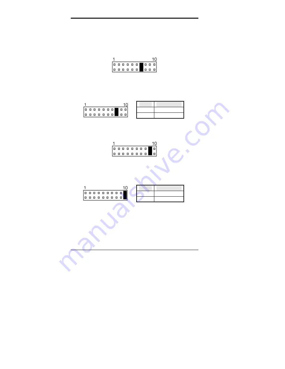
ATX Power ON Switch: Pins 7 and 17
This 2-pin connector is an “ATX Power Supply On/Off
Switch” on the system that connects to the power switch on
the case. When pressed, the power switch will force the
system to power on. When pressed again, it will force the
system to power off.
Turbo LED Connector: Pins 8 and 18
There is no turbo/deturbo function on the CPU card. The
Turbo LED on the control panel will always be On when
attached to this connector.
Pin #
Signal Name
8 5V
18 Ground
Reset Switch: Pins 9 and 19
The reset switch allows the user to reset the system without
turning the main power switch Off and then On.
Hard Disk Drive LED Connector: Pins 10 and 20
This connector connects to the hard drive activity LED on
control panel. This LED will flash when the HDD is being
accessed.
Pin #
Signal Name
10 HDD
20 5V
Содержание CI5VGM Series
Страница 4: ......
Страница 12: ...Chapter 1 Introduction 8 CI5VGM User s Manual Board Dimensions...
Страница 13: ...Chapter 1 Introduction CI5VGM User s Manual 9 This page is intentionally left blank...
Страница 19: ...Chapter 2 Installations CI5VGM User s Manual 15 Jumper Locations on the CI5VGM...
Страница 29: ...Chapter 2 Installations CI5VGM User s Manual 25 Connector Locations on the CI5VGM...
Страница 42: ...Chapter 3 BIOS Configuration 38 CI5VGM User s Manual This page was intentionally left blank...
Страница 83: ...Chapter 5 VGA Driver Installation Guide CI5VGM User s Manual 79 Step 2 Double click Display then click Settings...
Страница 89: ...Chapter 5 VGA Driver Installation Guide CI5VGM User s Manual 85 Step 2 Double click Display...
Страница 90: ...Chapter 5 VGA Driver Installation Guide 86 CI5VGM User s Manual Step 3 Click Settings...
Страница 91: ...Chapter 5 VGA Driver Installation Guide CI5VGM User s Manual 87 Step 4 Click Advanced...
Страница 92: ...Chapter 5 VGA Driver Installation Guide 88 CI5VGM User s Manual Step 5 Click Adapter...
Страница 93: ...Chapter 5 VGA Driver Installation Guide CI5VGM User s Manual 89 Step 6 Click Change...
Страница 97: ...Chapter 5 VGA Driver Installation Guide CI5VGM User s Manual 93 Step 13 After the files are copied click Finish...
Страница 98: ...Chapter 5 VGA Driver Installation Guide 94 CI5VGM User s Manual Step 12 Click Close...
Страница 104: ...Chapter 6 System Monitor Utility 100 CI5VGM User s Manual 2 Power displays the current voltage status...
Страница 105: ...Chapter 6 System Monitor Utility CI5VGM User s Manual 101 3 Memory displays the current memory usage status...
Страница 116: ...Chapter 7 LANDesk Client Manager 112 CI5VGM User s Manual This page is intentionally left blank...
Страница 120: ...Chapter 8 Ethernet Setup User s Guide 116 CI5VGM User s Manual 2 Click System 3 Click Device Manager...
Страница 122: ...Chapter 8 Ethernet Setup User s Guide 118 CI5VGM User s Manual 6 Click Driver 1...
Страница 123: ...Chapter 8 Ethernet Setup User s Guide CI5VGM User s Manual 119 7 Click Update Driver...
Страница 125: ...Chapter 8 Ethernet Setup User s Guide CI5VGM User s Manual 121 10 Click OK 11 Type A then click OK 12 Click OK...
Страница 132: ...Appendix 128 CI5VGM User s Manual Appendix A I O Port Address Map B Interrupt Request Lines IRQ...


