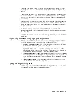
Press
the
reset
button
to
reset
the
server
and
run
the
power-on
self-test
(POST).
You
might
have
to
use
a
pen
or
the
end
of
a
straightened
paper
clip
to
press
the
button.
The
server
is
designed
so
that
LEDs
remain
lit
when
the
server
is
connected
to
an
ac
power
source
but
is
not
turned
on,
provided
that
the
power
supply
is
operating
correctly.
This
feature
helps
you
to
isolate
the
problem
when
the
operating
system
is
shut
down.
Any
memory,
microprocessor,
and
VRM
LED
can
be
lit
again
without
ac
power
after
you
remove
the
microprocessor
tray
so
that
you
can
isolate
a
problem.
After
ac
power
has
been
removed
from
the
server,
power
remains
available
to
these
LEDs
for
up
to
24
hours.
To
view
the
memory,
microprocessor,
and
VRM
LEDs,
press
and
hold
the
light-path-diagnostics
button
on
the
memory
card,
or
microprocessor
board
to
light
the
error
LEDs.
The
LEDs
that
were
lit
while
the
server
was
running
will
be
lit
again
while
the
button
is
pressed.
Diagnosing
problems
using
light
path
diagnostics
LEDs
in
three
locations
on
the
server
are
available
to
help
you
diagnose
problems
that
might
occur
during
installation.
Use
them
in
the
following
order:
1.
Operator
information
panel
-
Look
at
this
panel
first.
If
an
error
has
occurred,
the
information
LED
or
the
system-error
LED
is
lit.
Important:
If
the
server
has
a
baseboard
management
controller,
clear
the
BMC
log
and
system-event
log
after
you
resolve
all
conditions.
This
will
turn
off
the
information
LED
and
LOG
LED,
if
all
conditions
are
resolved.
2.
Light
path
diagnostics
panel
-
Move
the
latch
on
the
right
front
of
the
operator
information
panel
to
access
the
light
path
diagnostics
panel.
Note
any
LEDs
that
are
lit,
and
then
close
the
panel.
For
LED
locations,
see
the
illustration
on
page
48.
3.
LEDs
inside
the
server
-
To
identify
the
component
that
is
causing
the
error,
note
the
lit
LED
beside
or
on
the
component.
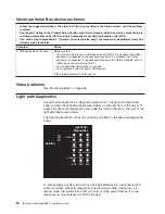
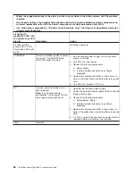
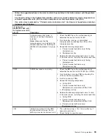
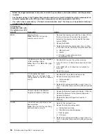
Light
path
diagnostics
panel
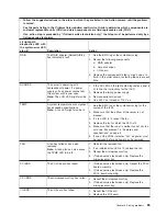
The
following
table
lists
the
LEDs
on
the
light
path
diagnostics
panel,
the
problems
that
they
indicate,
and
actions
to
solve
the
problems.
Chapter
6.
Solving
problems
61
Содержание 8863 - eServer xSeries 366
Страница 3: ...IBM xSeries 366 Type 8863 Installation Guide...
Страница 18: ...6 IBM xSeries 366 Type 8863 Installation Guide...
Страница 58: ...46 IBM xSeries 366 Type 8863 Installation Guide...
Страница 60: ...48 IBM xSeries 366 Type 8863 Installation Guide...
Страница 78: ...66 IBM xSeries 366 Type 8863 Installation Guide...
Страница 88: ...76 IBM xSeries 366 Type 8863 Installation Guide...
Страница 92: ...80 IBM xSeries 366 Type 8863 Installation Guide...
Страница 93: ......
Страница 94: ...Part Number 31R1515 Printed in USA 1P P N 31R1515...

