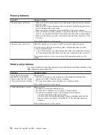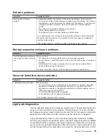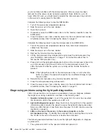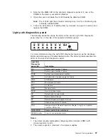
you
can
isolate
a
problem
with
the
microprocessors.
After
ac
power
has
been
removed
from
the
server,
power
remains
available
to
these
LEDs
for
up
to
24
hours.
After
24
hours,
you
might
need
to
reinstall
the
microprocessor
tray
and
turn
on
the
server
to
supply
power
to
the
LEDs.
Complete
the
following
steps
to
view
the
DIMM
LEDs:
1.
Turn
off
the
server
and
all
peripheral
devices.
2.
Slide
the
server
out
of
the
rack
cabinet.
3.
Open
the
top
cover.
4.
If
necessary,
open
the
DIMM
access
doors
on
the
memory
cassette
to
view
the
DIMM
LEDs.
5.
Close
the
server
cover;
then,
slide
the
server
into
the
rack
cabinet
and
connect
all
external
cables.
See
“Connecting
the
cables”
on
page
27.
Complete
the
following
steps
to
view
the
microprocessor
and
VRM
LEDs:
1.
Turn
off
the
server
and
all
peripheral
devices;
then,
disconnect
all
external
cables
from
the
server.
2.
Slide
the
server
out
of
the
rack
cabinet.
3.
Remove
the
fans
and
memory
cassette.
4.
Lift
the
microprocessor-tray
release
latch
and
remove
the
microprocessor
tray
(see
“Installing
a
microprocessor”
on
page
17
for
instructions
about
how
to
remove
the
microprocessor
tray).
5.
Press
and
hold
the
light-path-diagnostics
button
on
the
microprocessor
board
for
up
to
30
seconds
to
light
the
error
LEDs
on
the
microprocessor
board.
The
LEDs
that
were
lit
while
the
system
was
running
will
be
lit
while
the
button
is
pressed.
Note:
If
the
light-path-test
LED
on
the
microprocessor
tray
is
not
lit
when
the
button
is
pressed,
the
light-path
capacitor
has
insufficient
charge
to
light
the
error
LEDs.
6.
Reinstall
the
microprocessor
tray,
memory
cassette,
and
fans.
7.
Close
the
microprocessor-tray
release
latch.
8.
Close
the
server
cover;
then,
slide
the
server
into
the
rack
cabinet
and
connect
all
external
cables.
See
“Connecting
the
cables”
on
page
27.
Diagnosing
problems
using
the
light
path
diagnostics
LEDs
in
three
locations
on
the
server
are
available
to
help
you
diagnose
problems
that
might
occur
during
installation.
Use
them
in
the
following
order:
1.
Operator
information
panel
-
Look
at
this
panel
first.
If
an
error
has
occurred,
the
information
LED
or
the
system-error
LED
is
lit.
2.
Light
path
diagnostics
panel
-
Move
the
latch
on
the
right
front
of
the
operator
information
panel
and
pivot
the
panel
to
access
the
light
path
diagnostics
panel.
Note
any
LEDs
that
are
lit,
and
then
close
the
panel.
For
LED
locations,
see
the
illustration
on
page
34.
3.
LEDs
on
the
rear
of
the
server,
in
the
memory
cassette,
or
in
the
microprocessor
tray
-
To
identify
the
component
that
is
causing
the
error,
note
the
lit
LED
on
the
rear
of
the
server
or
beside
the
component.
The
following
example
illustrates
how
to
use
the
light
path
diagnostics
to
diagnose
a
system
error:
1.
The
system-error
LED
on
the
operator
information
panel
is
lit.
56
xSeries
365
Type
8861
and
8862:
Installation
Guide
Содержание 88625RX
Страница 3: ...xSeries 365 Type 8861 and 8862 Installation Guide ERserver...
Страница 54: ...42 xSeries 365 Type 8861 and 8862 Installation Guide...
Страница 56: ...44 xSeries 365 Type 8861 and 8862 Installation Guide...
Страница 90: ...78 xSeries 365 Type 8861 and 8862 Installation Guide...
Страница 98: ...86 xSeries 365 Type 8861 and 8862 Installation Guide...
Страница 101: ...W Web site server compatibility information 2 weight specifications 4 working inside a server with power on 7 Index 89...
Страница 102: ...90 xSeries 365 Type 8861 and 8862 Installation Guide...
Страница 103: ......
Страница 104: ...Part Number 25K9184 Printed in USA 1P P N 25K9184...


