background image

Appendix


B.


Related


service


information


149

Содержание 8480 - Eserver xSeries 205

Страница 1: ...IBM xSeries 205 Type 8480 Hardware Maintenance Manual and Troubleshooting Guide ERserver ...

Страница 2: ......

Страница 3: ...IBM xSeries 205 Type 8480 Hardware Maintenance Manual and Troubleshooting Guide ERserver ...

Страница 4: ...iodically made to the information herein these changes will be incorporated in new editions of the publication IBM may make improvements and or changes in the product s and or the program s described in this publication at any time This publication was developed for products and services offered in the United States of America IBM may not offer the products services or features discussed in this d...

Страница 5: ...cherheitshinweise bevor Sie eine Anweisung ausführen Accertarsi di leggere tutti gli avvisi di attenzione e di pericolo prima di effettuare qualsiasi operazione Lea atentamente todas las declaraciones de precaución y peligro ante de llevar a cabo cualquier operación WARNING Handling the cord on this product or cords associated with accessories sold with this product will expose you to lead a chemi...

Страница 6: ...iv IBM xSeries 205 Type 8480 Hardware Maintenance Manual and Troubleshooting Guide ...

Страница 7: ... operating system without ServerGuide 16 Configuring the Gigabit Ethernet controller 16 Using the SCSISelect Utility program 16 Starting the SCSISelect Utility program 17 SCSISelect menu choices 18 Using the Boot Menu program 18 Chapter 3 Diagnostics 21 General checkout 21 Checkout procedure 22 Diagnostic tools overview 23 POST 23 POST beep codes 24 Error logs 24 ServerGuide error symptoms 24 Smal...

Страница 8: ... non hot swap hard disk drive in bay 5 6 or 7 53 Installing a hot swap hard disk drive in bay 5 6 or 7 54 Installing memory modules 57 Installing a security rope clip 58 Replacing the side cover 59 Replacing the battery 60 Connecting external options 61 Video connector 62 Keyboard connector 62 Mouse connector 62 Parallel connector 62 Serial connectors 63 Gigabit Ethernet port 63 Universal Serial B...

Страница 9: ...A Getting help and technical assistance 117 Before you call 117 Using the documentation 117 Getting help and information from the World Wide Web 117 Software service and support 118 Hardware service and support 118 Appendix B Related service information 119 Safety information 119 General safety 119 Electrical safety 120 Safety inspection guide 121 Handling electrostatic discharge sensitive devices...

Страница 10: ...viii IBM xSeries 205 Type 8480 Hardware Maintenance Manual and Troubleshooting Guide ...

Страница 11: ...server Related publications This Hardware Maintenance Manual and Troubleshooting Guide contains information to help you solve the problem yourself or to provide helpful information to a service technician In addition to this Hardware Maintenance Manual and Troubleshooting Guide the following xSeries 205 Type 8480 documentation is provided with your server v Installation Guide This printed publicat...

Страница 12: ... v Note These notices provide important tips guidance or advice v Important These notices provide information or advice that might help you avoid inconvenient or problem situations v Attention These notices indicate possible damage to programs devices or data An attention notice is placed just before the instruction or situation in which damage could occur v Caution These statements indicate situa...

Страница 13: ...rt v Two serial ports v One parallel port v Two USB ports v Keyboard port v Mouse port v Audio ports Line out Line in Mic v Dual channel bus mastering IDE controller v Support for IBM Remote Supervisor Adapter Acoustical noise emissions v Sound power idling 5 1 bel maximum v Sound power operating 5 3 bel maximum Environment v Air temperature Server on 10 to 35 C 50 0 to 95 0 F Altitude 0 to 2133 m...

Страница 14: ... 1 Gbps LED Ethernet transmit receive activity LED Ethernet speed 1 Gbps LED When this LED on the Ethernet connector is lit it indicates that the Ethernet network speed is 1 Gbps When this LED is off it indicates that the Ethernet network speed is 10 Mbps or 100 Mbps CD eject button Press this button to release a CD from the CD ROM drive CD ROM drive activity LED When this LED is lit it indicates ...

Страница 15: ... blue Line out green Ethernet Video 1 1 2 2 Power cord connector Connect the power cord to this connector Mouse connector Connect a mouse or other PS 2 device to this connector Keyboard connector Connect a PS 2 keyboard to this connector Parallel connector Connect a parallel device to this connector Serial 2 connector Connect a 9 pin serial device to this connector Serial 1 connector Connect a 9 p...

Страница 16: ... it can be turned on in any of the following ways v You can press the power control button v If a power failure occurs while the server is turned on the server will restart automatically when power is restored v If your operating system supports the system management software for an optional Remote Supervisor Adapter the system management software can turn on the server v If your operating system ...

Страница 17: ...e When the server is connected to an ac power source but has not been turned on it is in Standby mode When the server is in Standby mode the operating system is not running and all core logic except for the service processor is shut down The power on LED flashes to indicate that the server is in Standby mode The server can respond to requests from the service processor such as a remote request to ...

Страница 18: ...8 IBM xSeries 205 Type 8480 Hardware Maintenance Manual and Troubleshooting Guide ...

Страница 19: ... installation See Using the ServerGuide Setup and Installation CD on page 13 for more information v Ethernet controller configuration process To configure the Ethernet controller see Configuring the Gigabit Ethernet controller on page 16 v SCSISelect Utility program some models If your server comes with a SCSI controller on the PCI extender card you can use the SCSISelect Utility program to config...

Страница 20: ... default setting for a menu item press F10 Using passwords The System Security choice appears only on the full Configuration Setup Utility menu After you select this choice you can implement an administrator password The administrator password provides access to all choices on the Configuration Setup Utility main menu You can set change or delete the administrator password The administrator passwo...

Страница 21: ...uide for instructions To set a user password complete the following steps 1 Set an administrator password See the instructions on page 10 2 Select User Password and press the Right Arrow key 3 Type the password you want to set in the Enter Password field and press Enter 4 Type the password again in the Enter Password Again field and press Enter 5 Press Enter to Set or Change Password The setting i...

Страница 22: ... original power on password will be reinstated 4 Connect the server to a power source keyboard monitor and mouse 5 Turn on the server You can now start the Configuration Setup Utility program and either delete the old password or set a new user password Enabling Broadcom NetXtreme Gigabit Ethernet Boot Agent The Broadcom NetXtreme Gigabit Ethernet Boot Agent is part of the BIOS code that comes wit...

Страница 23: ... to use interface with online help v Diskette free setup and configuration programs that are based on detected hardware v Performance Optimizer program which easily tunes your SCSI RAID adapter settings for your server environment v A system BIOS update program which updates the BIOS code directly from the CD v Device drivers that are provided for your server model and detected hardware ServerGuid...

Страница 24: ...he configuration programs For example The Express Configuration method runs the required programs for your server based on the hardware that is detected The Custom Configuration method displays all programs that are available for your server and you decide which programs to run The Replicated Configuration method provides the option of duplicating your setup selections to other servers that are th...

Страница 25: ...assed to the operating system installation program 3 With some operating system installations you can create an operating system replication diskette for setting up additional servers This diskette contains the Internet protocol IP address server name and other selections 4 If you are installing the operating system from diskette the ServerGuide program lists the diskettes that you must create and...

Страница 26: ...ntroller to operate at the appropriate rate In addition if the Ethernet ports that your server is connected to support auto negotiation the Gigabit Ethernet controller will set the appropriate duplex state That is the Ethernet controller will adjust to the network data rate whether the data rate is standard Ethernet 10BASE T Fast Ethernet 100BASE TX 1000BASE T half duplex HDX or full duplex FDX Th...

Страница 27: ...ISelect Utility prompt appears press Ctrl A Note If an administrator password has been set you are prompted to type the password to start the SCSISelect Utility program 3 When the Would you like to configure the host adapter or run the SCSI disk utility question appears make your selection and press Enter 4 Use the arrow keys to select a choice from the menu 5 Follow the instructions on the screen...

Страница 28: ...Maximum Sync Transfer Rate represents the transfer rate for Ultra SCSI devices The transfer rate for Ultra3 SCSI LVD devices is 160 MBps The transfer rate for Ultra2 SCSI LVD devices is 80 MBps The transfer rate for Fast SCSI devices is 20 MBps Advanced Configuration Options Select this choice to view or change the settings for advanced configuration options v SCSI Disk Utilities Select this choic...

Страница 29: ...e startup sequence of your server 1 Turn off the server 2 Restart the server 3 Press F12 4 Select the startup device The next time the server is started it returns to the startup sequence set in the Configuration Setup Utility program Chapter 2 Configuring your server 19 ...

Страница 30: ...20 IBM xSeries 205 Type 8480 Hardware Maintenance Manual and Troubleshooting Guide ...

Страница 31: ...efore you run diagnostics verify that the failing system is not part of a shared DASD cluster A system might be part of a cluster if v The system is identified as part of a cluster v One or more external storage units are attached to the system and at least one of the attached storage units is also attached to another system or unidentifiable source v One or more systems are located near the faili...

Страница 32: ...st error in the POST error codes on page 97 7 Check the System Error log If an error was recorded by the system see Chapter 6 Symptom to FRU index on page 85 8 Start the diagnostic programs 9 Check for the following responses v One beep v Readable instructions or the main menu 003 DID YOU RECEIVE BOTH OF THE CORRECT RESPONSES NO Find the failure symptom in Chapter 6 Symptom to FRU index on page 85...

Страница 33: ... can create a customized support page that is specific to your hardware complete with Frequently Asked Questions Parts Information Technical Hints and Tips and Downloadable files In addition you can choose to receive electronic mail e mail notifications whenever new information becomes available about your registered products After you register and profile your xSeries products you can diagnose pr...

Страница 34: ...in menu See Chapter 2 Configuring your server on page 9 for more information Viewing error logs from diagnostic programs Start the diagnostic programs select Hardware Info from the top of the diagnostic programs screen select System Error Log from the list that appears then follow the instructions on the screen See Starting the diagnostic programs on page 26 for more information ServerGuide error ...

Страница 35: ...od of testing the major components of your server Diagnostic error messages indicate that a problem exists they are not intended to be used to identify a failing part Troubleshooting and servicing of complex problems that are indicated by error messages should be performed by trained service personnel Sometimes the first error to occur causes additional errors In this case the server displays more...

Страница 36: ...because of the system configuration Warning This result occurs when a possible problem is reported during the diagnostic test such as when a device driver is not found test specific string is additional information that you can use to analyze the problem Starting the diagnostic programs The IBM Enhanced Diagnostics programs will isolate your server hardware from software that you have installed on...

Страница 37: ...owing to download the latest image of the IBM Enhanced Diagnostics from the World Wide Web and create a startable Enhanced Diagnostics diskette 1 Go to the following World Wide Web site http www ibm com pc support 2 Download the diagnostics file for your server to a hard disk drive directory not to a diskette 3 Go to a DOS prompt and change to the directory where the file was downloaded 4 Insert a...

Страница 38: ...iew Test Log from the list that appears then follow the instructions on the screen 6 You can save the test log to a file on a diskette or to your hard disk drive Note The system maintains the test log data while the system is powered on When you turn off the power to the server the test log is cleared Viewing the System Error log With the optional service processor adapter you can also view the Sy...

Страница 39: ...sword check jumpers 10 Replace the boot block and password check jumpers to their original positions 11 Replace any adapters that were removed 12 Replace the cover and reconnect all cables that were disconnected 13 Turn on the server to restart the operating system Power checkout Power problems can be difficult to solve For example a short circuit can exist anywhere on any of the power distributio...

Страница 40: ...ther a problem exists with the connector cable or hub The Ethernet transmit receive activity LED on the operator information panel is lit when the Ethernet controller sends or receives data over the Ethernet Network If the Ethernet transmit receive activity LED is off make sure that the hub and network are operating and that the correct device drivers are installed The Ethernet link status LED on ...

Страница 41: ...Duplex mode make sure that you also manually configure the speed v Reseat or replace the adapter The Ethernet transmit receive activity LED does not work Check the following v Make sure that you have loaded the network device drivers v The network might be idle Try sending data from this server Data is incorrect or sporadic Check the following v Make sure that you are using Category 5 or higher ca...

Страница 42: ...t display messages from certain device drivers The latest information available concerning these messages will be made available at the IBM Support Web site at http www ibm com pc support 32 IBM xSeries 205 Type 8480 Hardware Maintenance Manual and Troubleshooting Guide ...

Страница 43: ...pace around the front and rear of the server Do not place objects in front of the fans v You have followed the instructions for cabling provided with optional adapters v You have replaced a failed fan as soon as possible Major components of the IBM Eserver xSeries 205 Type 8480 The following illustration shows the locations of major components in the IBM Eserver xSeries 205 Type 8480 server Note T...

Страница 44: ...nd PCI extender board Depending on installed options your system board and PCI extender board might look slightly different Microprocessor and fan U6 AGP PCI 1 PCI 2 PCI 3 PCI 4 PCI 5 Battery DIMM 1 DIMM 2 34 IBM xSeries 205 Type 8480 Hardware Maintenance Manual and Troubleshooting Guide ...

Страница 45: ...nector CN3 Front fan connector CN2 Secondary IDE SEC IDE SCSI LED connector Primary IDE PRI IDE Diskette drive Wake on LAN connector Main power Microprocessor power Internal speaker connector Video connector Rear fan CN19 SCSI drive connector Password check JP1 jumper Boot block jumper JP6 CMOS clear jumper JP3 Chapter 4 Installing options 35 ...

Страница 46: ...following illustration shows the connectors and LEDs for the optional system management adapter that you can install in PCI slot 1 on the system board P P Ethernet link status LED green Ethernet port RJ 45 Ethernet activity LED green Error LED amber External power supply connector not used Serial port COM P P ASM Interconnect port RJ 14 Power LED green 36 IBM xSeries 205 Type 8480 Hardware Mainten...

Страница 47: ...stem to work properly Leave approximately 51 mm 2 in of open space around the front and rear of the server Do not place objects in front of the fans v You have followed the instructions for cabling provided with optional adapters v You have replaced a failed fan as soon as possible Handling static sensitive devices Attention Static electricity can damage electronic devices and your system To avoid...

Страница 48: ...ng position 1 Place the server on its side 2 Locate the release tab inside the foot then lift up on the tab Note The following illustration shows the rear feet located on the bottom rear of the server Release tab Release tab Feet unlocked position 3 Rotate the foot inward to the unlocked position then remove the foot from the server 38 IBM xSeries 205 Type 8480 Hardware Maintenance Manual and Trou...

Страница 49: ...Guides Guides 5 Rotate the foot outward until the foot locks into place 6 Complete steps 2 through 5 for each foot Attention When you need to access the inside of the server to install options you might find it easier to lay the server on its side If you do so make sure the feet are in the horizontal position see the previous steps Otherwise the feet might break off from the server because of the ...

Страница 50: ...on on page 119 2 Turn off the server and all attached devices 3 Disconnect all external cables and power cords 4 Pull the cover release latch away from the server and push the side cover toward the rear of the server Key lock Cover release latch To replace the side cover see Replacing the side cover on page 59 Attention For proper cooling and airflow replace the side cover before turning on the se...

Страница 51: ... access the existing option Complete the following steps to remove the frame support bracket 1 Pull out on the rear end of the frame support bracket approximately 150 mm 6 in 2 Pull the rear end of the frame support bracket away from the server and place the bracket aside To reinstall the frame support bracket reverse the previous steps Chapter 4 Installing options 41 ...

Страница 52: ...ersal PCI adapters it does not support 3 3 V adapters v Your server uses a rotational interrupt technique to configure PCI adapters Therefore you can install a variety of PCI adapters that currently do not support sharing of PCI interrupts v PCI slots 1 through 5 are on PCI bus 2 The system scans the AGP slot and PCI expansion slots 1 through 5 to assign system resources Then the system starts dev...

Страница 53: ...on 5 Rotate the rear adapter retaining bracket to the open unlocked position and remove it from the server 6 From the rear of the server press on the slot cover Grasp it and pull the expansion slot cover out of the expansion slot Store it in a safe place for future use Attention Expansion slot covers must be installed on all vacant slots This maintains the electronic emissions standards of the ser...

Страница 54: ...install do so now 11 If you have installed a full length adapter rotate the front adapter retaining bracket to the closed locked position 12 Reinstall the rear adapter retaining bracket then rotate the bracket to the closed locked position Note The rear adapter retaining bracket rests against the side cover You might find it easier to lay the server on its side to replace the side cover 13 Replace...

Страница 55: ... and PCI extender boards on page 34 for the location of the SCSI LED connector RAID adapter SCSI connector SCSI cable 4 If you have other adapters or options to install or remove do so now 5 Rotate the front adapter support bracket to the closed locked position 6 Reinstall the rear adapter support bracket then rotate it to the closed locked position 7 Replace the frame support bracket 8 Replace th...

Страница 56: ...this section are examples The cabling that you use for your server depends on your system configuration Notes 1 See the documentation that comes with your adapter for any cabling instructions 2 Cable identifiers are printed on the cables that come with your server and options Use these identifiers to connect the cables to the correct connectors For example the hard disk drive cables are labeled HD...

Страница 57: ... drive cage bays 5 to 7 to the internal channel connector on the RAID adapter RAID adapter SCSI connector SCSI cable 6 If you have other options to install or remove do so now otherwise go to Replacing the side cover on page 59 Chapter 4 Installing options 47 ...

Страница 58: ... v CD ROM or DVD ROM Internal drive bays The IBM Eserver xSeries 205 Type 8480 server comes with an IDE CD ROM or DVD ROM drive in bay 1 a 3 5 in 1 44 MB diskette drive in bay 3 and a hard disk drive installed in bay 4 Bay 1 Bay 2 Bay 3 Bay 4 Bay 5 Bay 6 Bay 7 48 IBM xSeries 205 Type 8480 Hardware Maintenance Manual and Troubleshooting Guide ...

Страница 59: ...ll a drive or PCI adapter save the EMC shield and filler panel from the bay or the PCI adapter slot cover in the event you later remove the option v For a complete list of supported options for your server go to http www ibm com pc support on the World Wide Web Preinstallation steps Before you install drives in your server verify that you have all the cables and other equipment specified in the do...

Страница 60: ...OM drive to the gray middle connector The narrower signal cable has two connectors one to attach to the diskette drive and the other to attach to the connector FDD1 on the system board If your server comes with a SCSI connector on the extender board and SCSI hard disk drive an Ultra160 twisted ribbon cable connects the internal Ultra160 SCSI hard disk drive to the SCSI connector on the PCI extende...

Страница 61: ...eld away from the server Note If you are installing a drive that contains a laser observe the following safety precaution Statement 3 CAUTION When laser products such as CD ROMs DVD ROM drives fiber optic devices or transmitters are installed note the following v Do not remove the covers Removing the covers of the laser product could result in exposure to hazardous laser radiation There are no ser...

Страница 62: ...ion of the IDE connectors see System board internal cable connectors on page 35 If the drive is a SCSI device connect one end of the SCSI signal cable into the back of the drive and the other end of the cable into the 68 pin connector on the PCI connector on the extender board Note Route the signal cable so that it does not block the airflow to the rear of the drives or over the microprocessor 12 ...

Страница 63: ...ving the frame support bracket on page 41 for details 5 If your server has hard disk drives preinstalled in the drive cage disconnect the power and signal cables from the rear of the drives 6 Rotate the drive cage out of the server until it locks into place with the drive cage retention tab The open ends of the drive slots and installed drives will face you Note Ensure that the drive cage locks in...

Страница 64: ...hard disk drive If a hot swap disk drive is connected to an optional hot swap RAID controller and if your hot swap drive becomes defective the RAID controller can rebuild the data from that drive onto another hot swap drive See the information that comes with your RAID controller for details Each hot swap drive has a green hard disk drive activity LED and an amber hard disk drive status LED When t...

Страница 65: ...as viewed from the front of the server Hard disk drive activity LED green Hard disk drive status LED amber SCSI hot swap hard disk drive connector Note The hard disk drive activity LED and hard disk drive status LED on the backplane match the hard disk drive activity LED and hard disk drive status LED on the hot swap drive The following illustration shows the rear connectors on the hot swap drive ...

Страница 66: ...hard disk in the hot swap bay a Ensure that the tray handle is open that is perpendicular to the drive b Align the drive tray assembly with the guide rails in the bay c Gently push the drive tray assembly into the bay until the drive stops d Push the tray handle to the closed locked position Filler panel Drive tray assembly Drive tray handle in open position e Check the hard disk drive status LED ...

Страница 67: ...onnect all external cables and power cords then remove the side cover See Removing the side cover on page 40 for details 3 Remove the frame support bracket See Removing the frame support bracket on page 41 4 Touch the static protective package containing the DIMM to any unpainted metal surface on the server Then remove the new DIMM from the package 5 Open the retaining clips and if necessary remov...

Страница 68: ... on page 119 2 Turn off the server and all attached devices Disconnect all external cables and power cords then remove the side cover See Removing the side cover on page 40 for details 3 Use a screwdriver to remove the two metal knockouts 4 Insert the rope clip through the rear panel then attach and tighten the nuts 5 Thread the cable through the rope clip and around an object that is not part of ...

Страница 69: ...s on the underside of the side cover match up to the holes along the sides of the server Press down on the cover release latch button as you close the cover release latch to lock the side cover Key lock Cover release latch 3 If you have not done so already make sure that the two front stabilizing feet are rotated outward so that they properly support the server Rotate each individual foot outward ...

Страница 70: ... frame support bracket See Removing the side cover on page 40 and Removing the frame support bracket on page 41 3 Complete the following steps to remove the battery a Use one fingernail to press the top of the battery clip away from the battery The battery pops up when released b Use your thumb and index finger to lift the battery from the socket 4 Complete the following steps to insert the new ba...

Страница 71: ...guidelines on page 37 review the safety precautions listed in Statement 1 and Statement 5 in Safety information on page 119 and read the documentation that comes with your options 2 Be sure that your server and all attached devices are turned off 3 Follow the instructions that come with the option to prepare it for installation and to connect it to the server This section provides information abou...

Страница 72: ...ctor that supports a mouse or other pointing device The mouse connector is located on the rear of your computer See System board external connectors on page 36 for the location of this connector 6 4 2 1 3 5 Parallel connector Your server has one 25 pin female D shell parallel connector This connector supports three standard Institute of Electrical and Electronics Engineers IEEE 1284 modes of opera...

Страница 73: ... LED and the Ethernet transmit receive activity LED on the rear of the server see the User s Guide Configuring the Gigabit Ethernet controller The Ethernet controller is a PCI Plug and Play device You do not need to set any jumpers or configure the controller for your operating system before you use the Ethernet controller However you must install a device driver to enable your operating system to...

Страница 74: ...s with a maximum of 127 external devices and a maximum signal distance of 5 meters 16 ft per segment You must use devices that support USB 2 0 in order to obtain this maximized data transfer rate Audio connectors The audio connectors are used to connect external audio equipment to your server Line out green Line in blue Mic pink Line out This connector is used to send audio signals from the server...

Страница 75: ...Remote Supervisor Adapter option documentation for detailed information about the advanced system management ASM interconnect network P P Ethernet link status light green Ethernet port RJ 45 Ethernet activity light green Error light amber External power supply connector not used Serial port COM P P ASM Interconnect port RJ 14 Power light green Chapter 4 Installing options 65 ...

Страница 76: ...66 IBM xSeries 205 Type 8480 Hardware Maintenance Manual and Troubleshooting Guide ...

Страница 77: ...ation describes procedures for removing and installing certain components inside the system Only a qualified service technician is authorized to access the components described in this section Important The field replaceable unit FRU procedures are intended for trained servicers who are familiar with IBM xSeries products See the parts listing in System on page 112 to determine if the component bei...

Страница 78: ... and disconnect all power cords and then all external cables 3 Remove the side cover see Removing the side cover on page 40 4 Press the bezel release latch at the top of the server to disconnect the top of the bezel from the server 5 Release the two tabs at the top edge of the bezel and pull the top of the bezel slightly away from the server 6 Pull the bezel up to release the two tabs at the botto...

Страница 79: ... cage outward until it locks in the vertical position so that you can reach through to the other side of the power switch and LED panel cable 7 To remove the power switch and LED panel press in on the tab on the left side of the panel then squeeze the top and bottom of the right side of the panel and carefully pull the panel away from the system 8 Note where the power switch and LED panel cable co...

Страница 80: ...siderations on page 33 To remove the hot swap backplane complete the following steps 1 Turn off the server if it is on 2 Unplug the server 3 Remove the front bezel See Removing the front bezel on page 68 4 Remove the side cover See Removing the side cover on page 40 5 Remove the support bracket assembly See Removing the side cover on page 40 6 Remove any hard disk drives or drive fillers from the ...

Страница 81: ...mbly from the processor as a single unit a Detach the fan sink cable b Loosen the two captive screws on either side in leaf spring enclosures of the fan sink c With the two captive screws loosened pivot the leaf spring assemblies outward and out of the notches on the fan sink assembly d Lift the fan sink up and out of the computer Note It may be necessary to gently twist the fan sink to loosen it ...

Страница 82: ...t swap hard disk drive complete the following steps 1 Turn off the server if it is on 2 Unplug the server 3 Remove the front bezel See Removing the front bezel on page 68 4 Remove the side cover See Removing the side cover on page 40 5 Remove the support bracket assembly See Removing the side cover on page 40 6 Remove any hard disk drives or drive fillers from the drives 7 Disconnect the hard disk...

Страница 83: ...ollowing 1 Turn off the server if it is on 2 Unplug the server 3 Remove the cover See Removing the side cover on page 40 4 Disconnect internal cables from the planar and drives 5 Remove the screws from the rear of the server 6 Gently move the power supply away from the chassis and lift it out of the server Chapter 5 Field replaceable units 73 ...

Страница 84: ...age 40 5 Remove the fan cable from the system board 6 Use side cutters to sever the four rubber extensions on the outside of the server 7 Gently pry the fan away from the server and lift it up and out 8 To install the new fan assembly place the fan in position at the rear of the server 9 Guide the rubber extensions through the apertures 10 Use needle nosed pliers to pull the extensions through the...

Страница 85: ...remove the system board complete the following steps 1 Turn off the server if it is on 2 Unplug the server 3 Remove the side cover See Removing the side cover on page 40 4 Remove the support bracket See Removing the side cover on page 40 5 Disconnect the video connector cable 6 Remove the extender card adapters see Installing an adapter on page 43 7 To remove the rear server foot press the foot lo...

Страница 86: ...extender card connector from the system board edge connector then tilt the extender card and remove it from the server To install an extender card reverse this procedure 76 IBM xSeries 205 Type 8480 Hardware Maintenance Manual and Troubleshooting Guide ...

Страница 87: ...plete the following steps 1 Turn off the server if it is on 2 Unplug the server 3 Remove the side cover See Removing the side cover on page 40 4 Remove the front bezel See Removing the front bezel on page 68 5 Remove the support bracket See Removing the side cover on page 40 6 Disconnect the cables 7 Remove the adapter cards and both adapter retaining brackets see Installing an adapter on page 43 ...

Страница 88: ...g steps 1 Turn off the server if it is on 2 Unplug the server 3 Remove the side cover See Removing the side cover on page 40 4 Disconnect the cables 5 Remove the screws from the CD ROM drive cage 6 Gently slide the CD ROM drive toward the front of the server and lift it out 78 IBM xSeries 205 Type 8480 Hardware Maintenance Manual and Troubleshooting Guide ...

Страница 89: ... complete the following steps 1 Turn off the server if it is on 2 Unplug the server 3 Remove the side cover See Removing the side cover on page 40 4 Disconnect the cables 5 Remove the screws from the diskette drive cage 6 Gently slide the floppy disk drive toward the front of the server and lift it out Chapter 5 Field replaceable units 79 ...

Страница 90: ...e cover See Removing the side cover on page 40 4 Remove the front bezel See Removing the front bezel on page 68 5 Remove the handle assembly See Handle assembly on page 82 6 Remove the top side cover See Top side cover on page 81 7 Press down on the tab 8 From the underside grasp the bezel release latch in the center and gently pull it back and away from the server 80 IBM xSeries 205 Type 8480 Har...

Страница 91: ... 3 Remove the side cover See Removing the side cover on page 40 4 Remove the front bezel See Removing the front bezel on page 68 5 Remove the handle assembly See Handle assembly on page 82 6 Remove the four screws from the back of the server and put them in a safe place 7 Using a screwdriver gently pry the cover away from the server in the rear and slide the unit away from the server Chapter 5 Fie...

Страница 92: ...handle a Carefully use a flat blade screwdriver to push in the tabs inside the plastic cover on the top of the system then remove the plastic cover Store the cover for possible future use b Grasp the metal handle and slide it toward the rear of the system to remove it from your system Store the metal handle for possible future use To remove the handle support complete the following steps 1 Turn of...

Страница 93: ...wing steps 1 Turn off the server if it is on 2 Unplug the server 3 Remove the side cover See Removing the side cover on page 40 4 Remove all adapters See Installing an adapter on page 43 5 Rotate the adapter retainer to the open position 6 Grasp the adapter retainer and gently slide the top and bottom tabs out of the notches Chapter 5 Field replaceable units 83 ...

Страница 94: ...84 IBM xSeries 205 Type 8480 Hardware Maintenance Manual and Troubleshooting Guide ...

Страница 95: ...Configuration problems can cause false errors and symptoms 2 For IBM devices not supported by this index refer to the manual for that device 3 Always start with General checkout on page 21 The symptom to FRU index lists symptoms errors and the possible causes The most likely cause is listed first Use this symptom to FRU index to help you decide which FRUs to have available when servicing the compu...

Страница 96: ...S write read test failed 1 Battery 2 System board 1 1 4 BIOS EEPROM checksum failed 1 Recover BIOS 2 System board 1 2 1 Programmable Interval Timer failed v System board 1 2 2 DMA page register test failed v System board 1 2 3 DMA page register write read failed v System board 1 2 4 RAM refresh verification failed 1 DIMM 2 System board 1 3 1 First 64K RAM test failed v DIMM v Memory adapter 1 3 2 ...

Страница 97: ... DIMM 2 System board 3 Battery 3 3 1 Memory size mismatch occurred 1 DIMM 2 System board 3 Battery 3 3 2 Critical SMBUS error occurred I2C error 1 Disconnect the server power cord from outlet wait 30 seconds and retry 2 System board 3 Microprocessor 4 DIMMs 5 DASD backplane 6 DASD power cable 3 3 3 No operational memory in system 1 Install or reseat the memory modules and then do a 3 boot reset Fo...

Страница 98: ...Error Log when the problem is found 1 System Error Log is 75 full clear the log 2 PFA alert check log for failure clear PFA alert remove ac power for at least 20 seconds reconnect then turn on the system 3 Run light path diagnostics FAN LED on The LED next to the failing DIMM is on 1 Failing fan 2 System board MEMORY LED on The LED next to the failing DIMM is on 1 Failing DIMM 2 System board CPU L...

Страница 99: ...dditional power supply or remove optional devices from the server NMI LED on 1 Restart the server 2 Check the System Error Log TEMPERATURE LED on 1 Ambient temperature must be within normal operating specifications See Features and specifications on page 3 2 Ensure fans are operating correctly 3 Examine System Error Log a System over recommended temperature v Information LED panel b DASD over reco...

Страница 100: ...Failed COM2 serial port test v System board 014 XXX 000 Failed parallel port test v System board 015 XXX 001 USB interface not found board damaged v System board 015 XXX 015 Failed USB external loopback test 1 Make sure the parallel port is not disabled 2 Run the USB external loopback test again 3 System board 015 XXX 198 USB device connected during USB test 1 Remove USB devices from USB1 and USB2...

Страница 101: ...9 XXX 002 Failed optional microprocessor test 1 VRM 2 for optional microprocessor 2 2 Optional microprocessor 2 166 198 000 System Management Aborted Unable to communicate with ASM It may be busy Run the test again 1 Run the diagnostic test again 2 Correct other error conditions and retry These include other failed system management tests and items logged in the System Error Log of the optional Re...

Страница 102: ... Management Failed Restart ASM Error After restarting ASM communication was lost Unplug and cold boot to reset ASM 1 Disconnect all server and option power cords from the server wait 30 seconds reconnect and retry 2 Reseat the Remote Supervisor Adapter in PCI slot 1 J14 3 Remote Supervisor Adapter 166 342 000 System Management Failed ASM adapter BIST indicate failed tests 1 Ensure the latest firmw...

Страница 103: ...ablish drive parameters 1 Check cable and termination 2 SCSI backplane 3 Hard disk 217 XXX 000 Failed BIOS hard disk test Note If RAID is configured the hard disk number refers to the RAID logical array v Hard disk 1 217 XXX 001 Failed BIOS hard disk test Note If RAID is configured the hard disk number refers to the RAID logical array v Hard disk 2 217 XXX 002 Failed BIOS hard disk test Note If RA...

Страница 104: ... determine if the SCSI bus is functioning properly 264 XXX 999 Errors on multiple tape drives see error text for more info v See error messages text in the PC Doctor error log for detailed information on each individual tape drive error 301 XXX 000 Failed keyboard test v Keyboard 405 XXX 000 Failed Ethernet test on controller on the system board 1 Verify that Ethernet is not disabled in BIOS 2 Sys...

Страница 105: ...is listed first Note See System on page 112 to determine which components should be replaced by a field service technician CD ROM drive problems Symptom FRU action Microprocessor test failed v Microprocessor System timer test failed v System board Memory test failed v DIMM v System board RAM refresh test failed v System board ECC controller logic v System board CMOS RAM test failed v System board ...

Страница 106: ...ermine which components should be replaced by a field service technician AC good LED DC good LED Description FRU action Off Off No power to system or ac problem 1 Check ac power to the system 2 Power supply On Off Standby mode or dc problem 1 Check system board cable connectors J4 and J10 Move switch 7 of SW 1 to bypass power control If the dc good LED is lit press Ctrl Alt Delete Watch the screen...

Страница 107: ...ettings and any additional desired settings then save the configuration 1 Run the Configuration Setup Utility program 2 Battery 3 Failing device 4 System board 163 Real time clock error 1 Run the Configuration Setup Utility program 2 Battery 3 System board 164 Memory configuration changed 1 Run the Configuration Setup Utility program 2 DIMM 3 System board 184 Power on password damaged 1 Run the Co...

Страница 108: ...stics 2 Diskette drive 3 Drive cable 4 System board 962 Parallel port error 1 Run the Configuration Setup Utility program 2 System board 11XX System board serial port 1 or 2 error 1 Run the Configuration Setup Utility program 2 System board 1762 Hard drive configuration error IDE only 1 Hard disk drive 2 Hard disk cables 3 Run the Configuration Setup Utility program 4 System board 178X Hard drive ...

Страница 109: ...r 1 Microprocessor 2 System board 00019701 Microprocessor 1 failed 1 Microprocessor 2 System board 00180200 No more I O space available for PCI adapter 1 Run the Configuration Setup Utility program 2 Adapter 3 System board 00180300 No more memory above 1MB for PCI adapter 1 Run the Configuration Setup Utility program 2 Adapter 3 System board 00180500 PCI option ROM checksum error 1 PCI adapter 2 S...

Страница 110: ...otes a SCSI channel cable details if any appear elsewhere in this publication b The adapter controller detects a configuration change Do not choose Save Changes Instead press F10 to bypass any options to this effect 2 If ISPR error is EF10 after disconnecting cables a Identify which channel is causing the error by the second digit Z of the original ISPR code as indicated in the following table Not...

Страница 111: ...oad jumpers on the controller and try to flash the firmware code to the card 2 Isolate between SCSI subsystem and controller by disconnecting all hard disk drive cables attached to the suspect card and reboot CAUTION Do not press F5 Doing so will change the server s configuration If ISPR code is EF10 after disconnecting cables follow the steps below until the error is eliminated a Identify which c...

Страница 112: ...20 ServeRAID 5i only 1 Remove the ServeRAID 5i controller from its slot and install it in the proper PCI option slot 2 Verify that the ServeRAID 5i controller is supported in this server 3 ServeRAID 5i controller 4 System board 3E2x 1 Reseat the ServeRAID controller 2 Flash latest level of BIOS code and firmware for controller 3 ServeRAID 5i controller 4 Integrated RAID controller on server 4xxx t...

Страница 113: ...ontroller Service processor error codes When viewed from POST service processor error codes will appear in hexadecimal form generally beginning with A2 A3 A4 A5 A6 A7 AD AE or E1 However when viewed from the System Error Log the messages will appear as text To determine a possible error condition for the service processor see the System Error Log see Viewing error logs from diagnostic programs on ...

Страница 114: ... 2 Replace power supply x System board is over recommended temperature level warning system board is over recommended temperature 1 Ensure system is being properly cooled see System reliability considerations on page 37 2 Replace the system board System board is under recommended temperature level warning system board is under recommended temperature v Ambient temperature must be within normal ope...

Страница 115: ... 1 Add another power supply 2 Remove options from system 3 System can continue to operate without redundancy protection if steps1 and 2 are not followed System under recommended voltage for x level warning indicated voltage supply under nominal value value for x can be 12 12 or 5 1 Check connections to the power subsystem 2 Power supply 3 Power cage assembly if installed System shutdown Refer to t...

Страница 116: ...nder temperature v Ambient temperature must be within normal operating specifications see Features and specifications on page 3 System shutoff due to DASD temperature sensor x level critical DASD area reported temperature outside recommended operating range v Ensure that the system is being properly cooled see System reliability considerations on page 37 System shutoff due to high ambient temperat...

Страница 117: ...Adapter in PCI slot 1 J14 and the remote supervisor adapter connector on the PCI riser card 2 Memory DIMMs 3 System board Failure reading 12C device Check devices on bus 1 1 Reseat the I2C cable between the operator information panel and system board J22 2 Operator information panel 3 System board Failure reading 12C device Check devices on bus 2 1 Reseat the cable between system board and the pow...

Страница 118: ...or device on the server Modem printer mouse or non IBM devices Each adapter Drives Memory modules minimum requirement 256 MB 2 banks of 128 MB DIMMs Note Minimum operating requirements are a One power supply b Power cage assembly if installed c System board d One microprocessor and VRM e Memory module with a minimum of two 128 MB DIMMs 4 Turn on the server If the problem remains suspect the follow...

Страница 119: ...v Diagnostics version Type and version level v Hardware configuration Print print screen configuration currently in use BIOS level v Operating system software Type and version level Note To eliminate confusion identical systems are considered identical only if they 1 Are the exact machine type and models 2 Have the same BIOS level 3 Have the same adapters attachments in the same locations 4 Have t...

Страница 120: ...110 IBM xSeries 205 Type 8480 Hardware Maintenance Manual and Troubleshooting Guide ...

Страница 121: ...Chapter 7 Parts listing Type 8480 This parts listing supports the xSeries 205 Type 8480 1 2 3 4 5 6 7 8 9 10 11 12 13 14 15 16 17 18 19 Copyright IBM Corp 2002 111 ...

Страница 122: ...12 Frame support bracket all models 19K4963 CRU 13 Cover side top all models 49P1965 CRU 14 Memory 128 MB ECC model 94x 95x 96x 10K0066 CRU 14 Memory 256 MB PC2100 ECC DIMM models 13x 22x 23x 2Ax 32x 33x 3Ax 42x 43x 4Ax 52x 53x 5Ax 93x 10K0068 CRU 14 Memory 512 MB DIMM model 4AG 10K0069 CRU 15 Heat sink fan assembly all models 32P4004 FRU 16 Microprocessor 400 1 8 128 models 93x 94x 58P9965 FRU 16...

Страница 123: ...bar all models 24P1746 FRU Microprocessor clip all models 49P1956 FRU Miscellaneous hardware kit all models v Screw M3 5 7 v Gasket EMC two position 1 v Bracket I O blank 1 v Bracket power supply 1 v Support blank isolator 4 v Bracket key holder 1 v Screw M3X5 slotted 4 v Clip 1 v Spacer system board 4 v Clamp SCSI cable 1 v Screw M3 5 slotted 6 09N5764 CRU Mouse assembly 2 button all models 24P03...

Страница 124: ... Canadian Standards Association CSA For units intended to be operated at 115 volts Use a UL listed and CSA certified cord set consisting of a minimum 18 AWG Type SVT or SJT three conductor cord a maximum of 15 feet in length and a parallel blade grounding type attachment plug rated 15 amperes 125 volts For units intended to be operated at 230 volts U S use Use a UL listed and CSA certified cord se...

Страница 125: ...r USSR Vietnam former Yugoslavia Zaire Zimbabwe 13F9997 Denmark 14F0015 Bangladesh Burma Pakistan South Africa Sri Lanka 14F0033 Antigua Bahrain Brunei Channel Islands China Hong Kong S A R Cyprus Dubai Fiji Ghana India Iraq Ireland Kenya Kuwait Malawi Malaysia Malta Nepal Nigeria Polynesia Qatar Sierra Leone Singapore Tanzania Uganda United Kingdom Yemen Zambia 14F0051 Liechtenstein Switzerland 1...

Страница 126: ...116 IBM xSeries 205 Type 8480 Hardware Maintenance Manual and Troubleshooting Guide ...

Страница 127: ...es and IntelliStation systems operating systems and programs come with information that contains troubleshooting procedures and explanations of error messages and error codes If you suspect a software problem see the information for the operating system or program Using the documentation Information about your IBM xSeries or IntelliStation system and preinstalled software if any is available in th...

Страница 128: ...usage configuration and software problems with xSeries servers IntelliStation workstations and appliances For information about which products are supported by Support Line in your country or region go to http www ibm com services sl products For more information about Support Line and other IBM services go to http www ibm com services or go to http www ibm com planetwide for support telephone num...

Страница 129: ...causes hazards to the customer or that makes the equipment unsafe v Before you start the machine ensure that other service representatives and the customer s personnel are not in a hazardous position v Place removed covers and other parts in a safe place away from all personnel while you are servicing the machine v Keep your tool case away from walk areas so that other people will not trip over it...

Страница 130: ...installing main units v Before you start to work on the machine unplug the power cord If you cannot unplug it ask the customer to power off the wall box that supplies power to the machine and to lock the wall box in the off position v If you need to work on a machine that has exposed electrical circuits observe the following precautions Ensure that another person familiar with the power off contro...

Страница 131: ...and service personnel from injury This guide addresses only those items However good judgment should be used to identify potential safety hazards due to attachment of non IBM features or options not covered by this inspection guide If any unsafe conditions are present you must determine how serious the apparent hazard could be and whether you can continue without first correcting the problem Consi...

Страница 132: ...s until they are inserted into the product v Avoid contact with other people v Wear a grounded wrist strap against your skin to eliminate static on your body v Prevent the part from touching your clothing Most clothing is insulative and retains a charge even when you are wearing a wrist strap v Use the black side of a grounded work mat to provide a static free work surface The mat is especially us...

Страница 133: ...lation maintenance or reconfiguration of this product during an electrical storm v Connect all power cords to a properly wired and grounded electrical outlet v Connect to properly wired outlets any equipment that will be attached to this product v When possible use one hand only to connect or disconnect signal cables v Never turn on any equipment when there is evidence of fire water or structural ...

Страница 134: ...ves fiber optic devices or transmitters are installed note the following v Do not remove the covers Removing the covers of the laser product could result in exposure to hazardous laser radiation There are no serviceable parts inside the device v Use of controls or adjustments or performance of procedures other than those specified herein might result in hazardous radiation exposure DANGER Some las...

Страница 135: ...plied to the device The device also might have more than one power cord To remove all electrical current from the device ensure that all power cords are disconnected from the power source 1 2 Statement 10 CAUTION Do not place any object weighing more than 82 kg 180 lbs on top of rack mounted devices Appendix B Related service information 125 ...

Страница 136: ...necte todos os equipamentos ao qual esse produto será conectado a tomadas corretamente instaladas v Sempre que possível utilize apenas uma das mãos para conectar ou desconectar cabos de sinal v Nunca ligue qualquer equipamento quando existir evidência de danos por fogo água ou na estrutura v Desconecte cabos de alimentação sistemas de telecomunicação redes e modems antes de abrir as tampas dos dis...

Страница 137: ...a bateria pelo correio para a IBM Instrução 3 PRECAUCIÓN Quando produtos a laser unidades de CD ROM unidades de DVD dispositivos de fibra ítica transmissores etc estiverem instalados observe o seguinte v Não remova as tampas A remoção das tampas de um produto a laser pode resultar em exposição prejudicial à radiação de laser Nenhuma peça localizada no interior do dispositivo pode ser consertada v ...

Страница 138: ...fornecida ao dispositivo O dispositivo também pode ter mais de um cabo de alimentação Para remover toda a corrente elétrica do dispositivo assegure que todos os cabos de alimentação estejam desconectados da fonte de energia elétrica 1 2 Instrução 10 CUIDADO Não coloque nenhum objeto com peso superior a 82 kg 180 lbs sobre dispositivos montados em rack 128 IBM xSeries 205 Type 8480 Hardware Mainten...

Страница 139: ...Appendix B Related service information 129 ...

Страница 140: ...130 IBM xSeries 205 Type 8480 Hardware Maintenance Manual and Troubleshooting Guide ...

Страница 141: ...Appendix B Related service information 131 ...

Страница 142: ...132 IBM xSeries 205 Type 8480 Hardware Maintenance Manual and Troubleshooting Guide ...

Страница 143: ...Appendix B Related service information 133 ...

Страница 144: ...134 IBM xSeries 205 Type 8480 Hardware Maintenance Manual and Troubleshooting Guide ...

Страница 145: ...Appendix B Related service information 135 ...

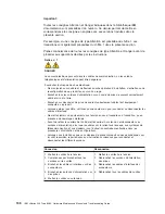
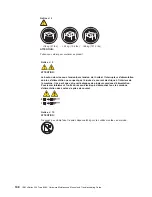
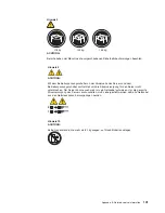
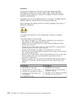
Страница 146: ...onnecté à ce produit v Lorsque cela est possible n utilisez qu une seule main pour connecter ou déconnecter les câbles d interface v Ne mettez jamais un équipement sous tension en cas d incendie ou d inondation ou en présence de dommages matériels v Avant de retirer les carters de l unité mettez celle ci hors tension et déconnectez ses cordons d alimentation ainsi que les câbles qui la relient aux...

Страница 147: ...ON Si des produits laser sont installés tels que des unités de CD ROM ou de DVD des périphériques contenant des fibres optiques ou des émetteurs récepteurs prenez connaissance des informations suivantes v N ouvrez pas ces produits pour éviter une exposition directe au rayon laser Vous ne pouvez effectuer aucune opération de maintenance à l intérieur v Pour éviter tout risque d exposition au rayon ...

Страница 148: ...pas l arrivée de courant électrique à l intérieur de la machine Il se peut que votre unité dispose de plusieurs cordons d alimentation Pour isoler totalement l unité du réseau électrique débranchez tous les cordons d alimentation des socles de prise de courant 1 2 Notice n 10 ATTENTION Ne posez pas d objet dont le poids dépasse 82 kg sur les unités montées en armoire 138 IBM xSeries 205 Type 8480 ...

Страница 149: ...steckdosen mit ordnungsgemäß geerdetem Schutzkontakt anschließen v Signalkabel möglichst einhändig anschließen oder lösen v Keine Geräte einschalten wenn die Gefahr einer Beschädigung durch Feuer Wasser oder andere Einflüsse besteht v Die Verbindung zu den angeschlossenen Netzkabeln Telekommunikationssystemen Netzwerken und Modems ist vor dem öffnen des Gehäuses zu unterbrechen Es sei denn dies is...

Страница 150: ...sfaserkabeln oder Transmitter installiert ist beachten Sie folgendes v Das Entfernen der Abdeckungen des CD ROM Laufwerks kann zu gefährlicher Laserstrahlung führen Es befinden sich keine Teile innerhalb des CD ROM Laufwerks die vom Benutzer gewartet werden müssen Die Verkleidung des CD ROM Laufwerks nicht öffnen v Steuer und Einstellelemente sowie Verfahren nur entsprechend den Anweisungen im vor...

Страница 151: ...ungsschalter am Netzteil wird die Stromversorgung für den Server nicht unterbrochen Der Server könnte auch mehr als ein Netzkabel aufweisen Um die gesamte Stromversorgung des Servers auszuschalten muß sichergestellt werden daß alle Netzkabel aus den Netzsteckdosen herausgezogen wurden 1 2 Hinweis 10 ACHTUNG Keine Gegenstände die mehr als 82 kg wiegen auf Rack Einheiten ablegen Appendix B Related s...

Страница 152: ...tura collegata a questo prodotto ad una presa elettrica correttamente cablata e munita di terra di sicurezza v Quando possibile collegare o scollegare i cavi di segnale con una sola mano v Non accendere qualsiasi apparecchiatura in presenza di fuoco acqua o se sono presenti danni all apparecchiatura stessa v Scollegare i cavi di alimentazione i sistemi di telecomunicazioni le reti e i modem prima ...

Страница 153: ...izioni nazionali e locali Avviso 3 ATTENZIONE Quando si installano prodotti laser come ad esempio le unità DVD CD ROM a fibre ottiche o trasmettitori prestare attenzione a quanto segue v Non rimuovere i coperchi L apertura dei coperchi di prodotti laser può determinare l esposizione a radiazioni laser pericolose All interno delle unità non vi sono parti su cui effettuare l assistenza tecnica v L u...

Страница 154: ...disattiva la corrente elettrica fornita all unità L unità potrebbe disporre di più di un cavo di alimentazione Per disattivare la corrente elettrica dall unità accertarsi che tutti i cavi di alimentazione siano scollegati dalla sorgente di alimentazione 1 2 Avviso 10 ATTENZIONE Non poggiare oggetti che pesano più di 82 kg sulla parte superiore delle unità montate in rack 144 IBM xSeries 205 Type 8...

Страница 155: ...Appendix B Related service information 145 ...

Страница 156: ...146 IBM xSeries 205 Type 8480 Hardware Maintenance Manual and Troubleshooting Guide ...

Страница 157: ...Appendix B Related service information 147 ...

Страница 158: ...148 IBM xSeries 205 Type 8480 Hardware Maintenance Manual and Troubleshooting Guide ...

Страница 159: ...Appendix B Related service information 149 ...

Страница 160: ...150 IBM xSeries 205 Type 8480 Hardware Maintenance Manual and Troubleshooting Guide ...

Страница 161: ...s de alimentaciín con un cableado correcto cualquier equipo que vaya a estar conectado a este producto v Si es posible utilice una sola mano cuando conecte o desconecte los cables de sent al v No encienda nunca un equipo cuando haya riesgos de incendio de inundaciín o de daños estructurales v Desconecte los cables de alimentaciín sistemas de telecomunicaciones redes y mídems conectados antes de ab...

Страница 162: ...ocal Declaración 3 PRECAUCIÓN Cuando instale productos láser como por ejemplo CD ROM unidades DVD dispositivos de fibra íptica o transmisores tenga en cuenta las advertencias siguientes v No retire las cubiertas Si retira las cubiertas del producto láser puede quedar expuesto a radiaciín láser perjudicial Dentro del dispositivo no existe ninguna pieza que requiera mantenimiento v El uso de control...

Страница 163: ...a corriente eléctrica suministrada al dispositivo Es posible también que el dispositivo tenga más de un cable de alimentaciín Para eliminar la corriente eléctrica del dispositivo asegúrese de desconectar todos los cables de alimentaciín de la fuente de alimentaciín 1 2 Declaración 10 PRECAUCIÓN No coloque ningún objeto que pese más de 82 kg 180 libras encima de los dispositivos montados en bastido...

Страница 164: ...154 IBM xSeries 205 Type 8480 Hardware Maintenance Manual and Troubleshooting Guide ...

Страница 165: ... ANY KIND EITHER EXPRESS OR IMPLIED INCLUDING BUT NOT LIMITED TO THE IMPLIED WARRANTIES OF NON INFRINGEMENT MERCHANTABILITY OR FITNESS FOR A PARTICULAR PURPOSE Some jurisdictions do not allow disclaimer of express or implied warranties in certain transactions therefore this statement may not apply to you This information could include technical inaccuracies or typographical errors Changes are peri...

Страница 166: ... and Windows NT are trademarks of Microsoft Corporation in the United States other countries or both UNIX is a registered trademark of The Open Group in the United States and other countries Java and all Java based trademarks and logos are trademarks or registered trademarks of Sun Microsystems Inc in the United States other countries or both Other company product or service names may be trademark...

Страница 167: ...sposal This unit contains materials such as circuit boards cables electromagnetic compatibility gaskets and connectors which may contain lead and copper beryllium alloys that require special handling and disposal at end of life Before this unit is disposed of these materials must be removed and recycled or discarded according to applicable regulations IBM offers product return programs in several ...

Страница 168: ...lt an IBM authorized dealer or service representative for help Properly shielded and grounded cables and connectors must be used in order to meet FCC emission limits Proper cables and connectors are available from IBM authorized dealers IBM is not responsible for any radio or television interference caused by using other than recommended cables and connectors or by unauthorized changes or modifica...

Страница 169: ...er cords used in the United States and Canada are listed by Underwriter s Laboratories UL and certified by the Canadian Standards Association CSA For units intended to be operated at 115 volts Use a UL listed and CSA certified cord set consisting of a minimum 18 AWG Type SVT or SJT three conductor cord a maximum of 15 feet in length and a parallel blade grounding type attachment plug rated 15 ampe...

Страница 170: ...stan Vanuatu Vietnam Wallis and Futuna Yugoslavia Federal Republic of Zaire 13F9997 Denmark 14F0015 Bangladesh Lesotho Maceo Maldives Namibia Nepal Pakistan Samoa South Africa Sri Lanka Swaziland Uganda 14F0033 Abu Dhabi Bahrain Botswana Brunei Darussalam Channel Islands China Hong Kong S A R Cyprus Dominica Gambia Ghana Grenada Iraq Ireland Jordan Kenya Kuwait Liberia Malawi Malaysia Malta Myanma...

Страница 171: ...da Bolivia Caicos Islands Canada Cayman Islands Colombia Costa Rica Cuba Dominican Republic Ecuador El Salvador Guam Guatemala Haiti Honduras Jamaica Mexico Micronesia Federal States of Netherlands Antilles Nicaragua Panama Peru Philippines Saudi Arabia Thailand Taiwan United States of America Venezuela Appendix C Notices 161 ...

Страница 172: ...162 IBM xSeries 205 Type 8480 Hardware Maintenance Manual and Troubleshooting Guide ...

Страница 173: ......

Страница 174: ... Part Number 59P2108 1P P N 59P2108 ...

Отзывы: