1-31
INSTALLATION
SFC BOILER / WATER HEATERS - SFC 199
•
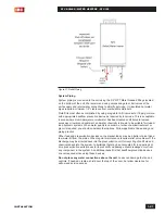
Between the unit’s outlet and any isolation valve to ensure the pressure
relief valve cannot be isolated by closing a valve. We recommend a valve kit
designed for this purpose to reduce installation time and to reduce the space
required.
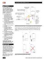
If required by local code, you can install a field-supplied domestic hot water
thermostatic mixing valve on the outlet of the SFC Series unit to prevent excessively
hot water from reaching a faucet if the unit is used in a high temperature heating
system. If the unit is being used to heat a low temperature heating system like a
radiant floor at temperatures at or below 120°F/49°C then the thermostatic mixing
valve may not be needed
.
Do not cap off the hot and cold piping connections if
they are not being used.
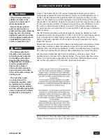
The SFC series units can be connected to the pressurized 1/2" or larger domestic
cold water supply piping and the domestic hot water piping in the home. The
minimum domestic water pressure required is 40PSI and recommended to be
50PSI or higher. Generating domestic hot water with a water pressure lower than
40PSI reduces the amount of hot water generated and increases the risk of scaling
in the heat exchanger.
The domestic water piping must be installed with isolation valves and flushing taps
installed on both the cold and hot domestic connections.
Thermal expansion of the water in the domestic hot water piping and unit can cause
excessive pressures to build in the piping system. This can cause the pressure
relief valve to discharge on a regular basis. This condition must be prevented with
the installation of a properly sized and installed domestic water expansion tank or
other device designed for the purpose.
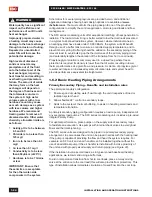
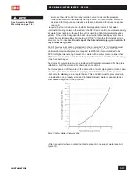
Table 7: Water Heater Pressure Drop
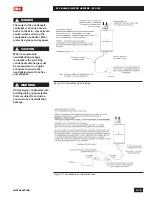
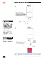
A filter is required where contanminants are present in the supply water (see A in
Figure 31).
NOTE
See Domestic Hot Water
Warnings on page 1-29.
Содержание SFC-199
Страница 46: ...INSTALLATION AND OPERATION INSTRUCTIONS 1 38 SFC BOILER WATER HEATERS SFC 199 PAGE INTENTIONALLY LEFT EMPTY...
Страница 54: ...INSTALLATION AND OPERATION INSTRUCTIONS 2 8 SFC BOILER WATER HEATERS SFC 199 PAGE INTENTIONALLY LEFT EMPTY...
Страница 75: ...6 1 DIAGRAMS SFC BOILER WATER HEATERS SFC 199 6 0 DIAGRAMS 6 1 PARTS DIAGRAMS 6 2 WIRING DIAGRAMS...
Страница 79: ...6 5 DIAGRAMS SFC BOILER WATER HEATERS SFC 199 6 2 WIRING DIAGRAMS Diagram 6 2 1 Pictorial wiring diagram...
Страница 81: ...SERVICE RECORD DATE LICENSED CONTRACTOR DESCRIPTION OF WORK DONE...

