1-11
INSTALLATION
SFC BOILER / WATER HEATERS - SFC 199
1.4.6 Sidewall Vent Termination
Direct Vent - Two Pipe
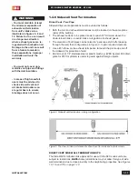
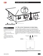
Sidewall direct vent applications must be vented as follows:
•
Both the inlet and exhaust terminations must be located on the same plane
(side) of the building.
•
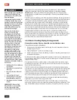
The exhaust outlet is to be placed so as to reach 12" minimum above the
down-turned intake - to avoid intake re-ingestion of exhaust gases.
•
The elevation of both pipes can be raised in “periscope style” after passing
through the wall, then configured as in
Figure 8,
to gain required clearance.
•
Use a 45° elbow on the exhaust termination to launch the plume up and off
the sidewall, for protection of wall.
•
Bird screen of 1/4" stainless steel or plastic mesh eg. (IPEX System 636 drain
grate for CPVC systems) is useful to guard against foreign objects.
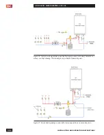
Figure 8: Sidewall vent termination - piping configuration
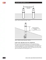
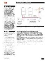
Figure 9: Top view - minimum distance of exhaust vent to inside and outside corners.
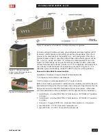
DIRECT VENT SIDE WALL TERMINATION KITS
The Side Wall Termination kits approved for use with the SFC series units are
subject to restrictions.
NOTE:
Some jurisdictions may not allow this type of side
wall termination due to close proximity to the neighboring properties.
See Figures
10, 11a and 11b on page 1-12.
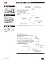
WARNINGS
- You must maintain at least
the minimum separation of
exhaust vent termination
from unit’s intake air as
illustrated in figures 5, 8 and
12. Failure to do so can result
in a dangerous situation
where exhaust gases are re-
ingested with combustion air.
Damage to the unit can result
from a failure to maintain
these separations. Improper
installation will void the
warranty.
- You must not cover non-
metallic vent pipe and fittings
with thermal insulation.
- In areas of high snowfall,
users must be advised to
check side wall vent and
air intake terminations on
a regular basis to ensure
blockage does not occur.
Содержание SFC-199
Страница 46: ...INSTALLATION AND OPERATION INSTRUCTIONS 1 38 SFC BOILER WATER HEATERS SFC 199 PAGE INTENTIONALLY LEFT EMPTY...
Страница 54: ...INSTALLATION AND OPERATION INSTRUCTIONS 2 8 SFC BOILER WATER HEATERS SFC 199 PAGE INTENTIONALLY LEFT EMPTY...
Страница 75: ...6 1 DIAGRAMS SFC BOILER WATER HEATERS SFC 199 6 0 DIAGRAMS 6 1 PARTS DIAGRAMS 6 2 WIRING DIAGRAMS...
Страница 79: ...6 5 DIAGRAMS SFC BOILER WATER HEATERS SFC 199 6 2 WIRING DIAGRAMS Diagram 6 2 1 Pictorial wiring diagram...
Страница 81: ...SERVICE RECORD DATE LICENSED CONTRACTOR DESCRIPTION OF WORK DONE...

