INSTALLATION AND OPERATION INSTRUCTIONS
5-4
SFC BOILER / WATER HEATERS - SFC 199
5.2.5 Flue Gas Temperature Sensor
This sensor ensures that the unit shuts down safely if the heat exchanger or the
venting system becomes blocked.
The flue gas temperature sensor is located at the top of the rear flue passage,
below the top panel. To remove the sensor, unclip from the wiring harness and
unscrew from the rear flue passage.
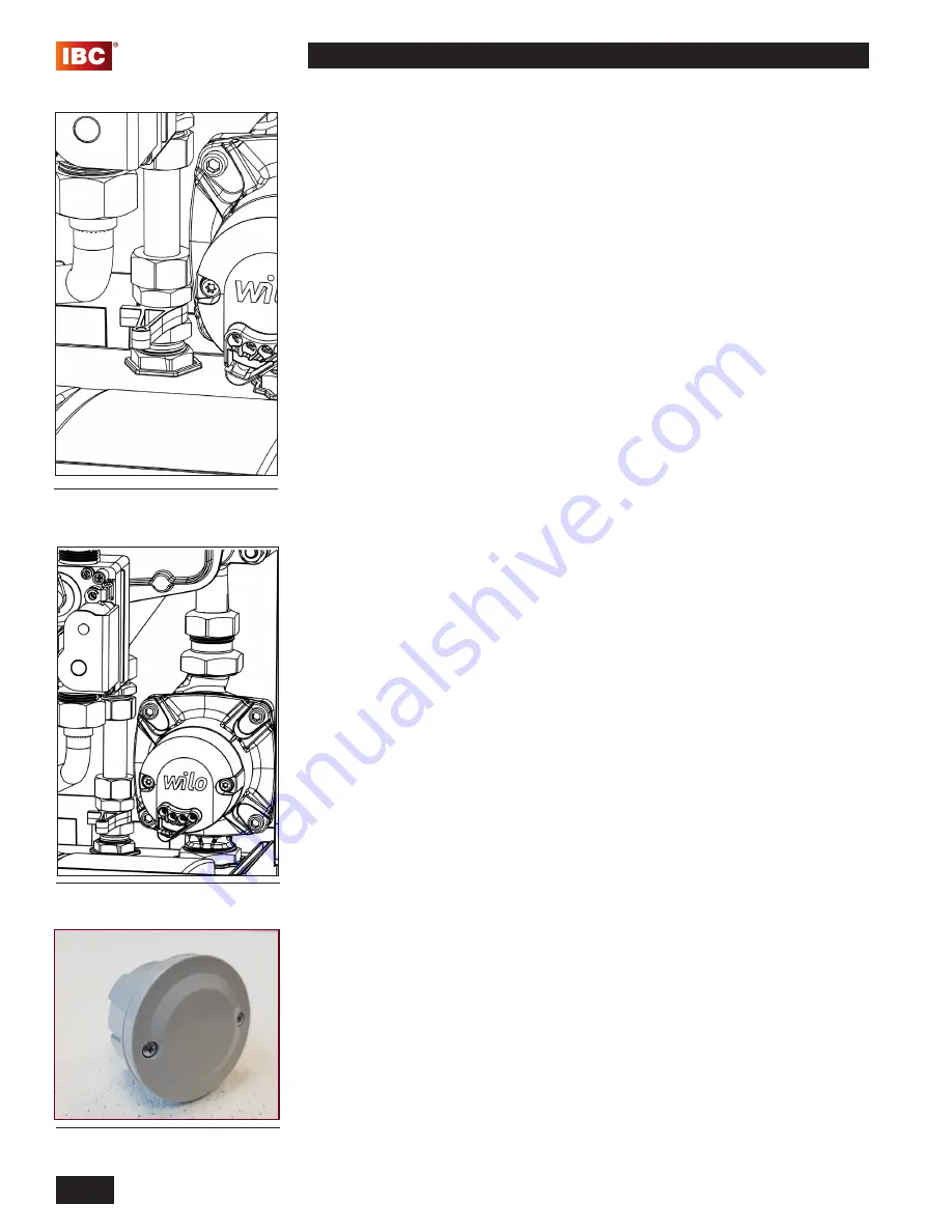
5.2.6 Domestic Hot Water Flow Sensor
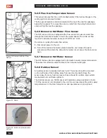
The SFC series units are equipped with a flow sensor to measure water flow
through the domestic hot water circuit in the water heater. The minimum flow
required to activate the water heater is 0.5 GPM or 2 L/min.
To service or replace the water flow sensor:
1.
Disconnect power to the unit.
2.
Turn off the cold and hot water valves below the unit, release the water
pressure and then drain the domestic hot water circuit. Leave the drain valves
open.
5.2.7 Domestic Hot Water Sensor
The SFC Series units are equipped with a domestic hot water temperature sensor.
The sensor is surface-mounted located on the hot water outlet pipe.
5.2.8 Outdoor Sensor
An outdoor sensor is supplied with each unit. The sensor should be mounted
on the north side of the building away from any direct sunlight. Keep the
sensor away from any heat sources such as exhaust fan outlets, dryer outlets,
mechanical room ventilation grills etc.
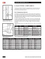
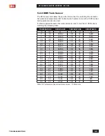
The Outdoor sensor is a 12KΩ sensor with resistance values as listed in Table
15. If the sensor is not connected to the unit, the unit operates at the unit’s supply
temperature set in the User Setup menu, and operates as a set point load.
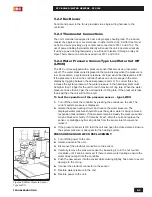
Figure 51: Pump
Figure 50: Domestic Water Flow
Sensor
Figure 52: Outdoor air temperature
sensor
Содержание SFC-199
Страница 46: ...INSTALLATION AND OPERATION INSTRUCTIONS 1 38 SFC BOILER WATER HEATERS SFC 199 PAGE INTENTIONALLY LEFT EMPTY...
Страница 54: ...INSTALLATION AND OPERATION INSTRUCTIONS 2 8 SFC BOILER WATER HEATERS SFC 199 PAGE INTENTIONALLY LEFT EMPTY...
Страница 75: ...6 1 DIAGRAMS SFC BOILER WATER HEATERS SFC 199 6 0 DIAGRAMS 6 1 PARTS DIAGRAMS 6 2 WIRING DIAGRAMS...
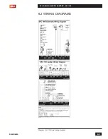
Страница 79: ...6 5 DIAGRAMS SFC BOILER WATER HEATERS SFC 199 6 2 WIRING DIAGRAMS Diagram 6 2 1 Pictorial wiring diagram...
Страница 81: ...SERVICE RECORD DATE LICENSED CONTRACTOR DESCRIPTION OF WORK DONE...

