3-5
STARTUP AND COMMISSIONING
SFC BOILER / WATER HEATERS - SFC 199
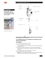
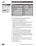
Figure 43: Back Flow Valve
Figure 44: Blower and Gas Valve Assembly
WARNING
Each SFC series unit is
equipped with a back flow
valve installed at the outlet of
the fan. Inspect the back flow
flapper annually.
3.4.1 Gaining access to combustion chamber, burner
removal instructions
DISASSEMBLY
1.
Turn off the main power switch to the unit.
2.
Turn off the gas supply valve to the unit.
There is no need to drain the unit unless the unit will be exposed to freezing
conditions while off.
3.
Remove the front door, and allow the unit to cool. Place a plastic barrier
over the bottom of the boiler cabinet to protect the electronics beneath from
condensate.
4.
Unplug the electrical connectors at the gas valve and fan.
5.
Loosen the lower gas valve connection nut.
NOTE:
There is an O-ring in the lower gas connection. Cover the gas piping
connections to prevent debris from entering the gas piping.
Содержание SFC-199
Страница 46: ...INSTALLATION AND OPERATION INSTRUCTIONS 1 38 SFC BOILER WATER HEATERS SFC 199 PAGE INTENTIONALLY LEFT EMPTY...
Страница 54: ...INSTALLATION AND OPERATION INSTRUCTIONS 2 8 SFC BOILER WATER HEATERS SFC 199 PAGE INTENTIONALLY LEFT EMPTY...
Страница 75: ...6 1 DIAGRAMS SFC BOILER WATER HEATERS SFC 199 6 0 DIAGRAMS 6 1 PARTS DIAGRAMS 6 2 WIRING DIAGRAMS...
Страница 79: ...6 5 DIAGRAMS SFC BOILER WATER HEATERS SFC 199 6 2 WIRING DIAGRAMS Diagram 6 2 1 Pictorial wiring diagram...
Страница 81: ...SERVICE RECORD DATE LICENSED CONTRACTOR DESCRIPTION OF WORK DONE...


