INSTALLATION AND OPERATION INSTRUCTIONS
1-30
SFC BOILER / WATER HEATERS - SFC 199
1.7.1 Domestic Hot Water System
The SFC series units have an independent piping circuit for efficiently generating
Domestic Hot Water. When a faucet is opened to draw hot water, water flow is
detected with a flow sensor and the SFC Series unit fires up to begin generating
domestic hot water. Due to the unique design of the unit’s heat exchanger, the unit
can fire with either no water in the space heating circuit or without flow of water if
pressurized with the domestic heating system water.
The heat exchanger has two separate copper water passageways encased in the
aluminum heat transfer block. Each copper passageway is completely isolated
from the other to eliminate cross contamination in the event of a leak. This heat
exchanger complies with the double wall heat exchanger requirements in many
regional jurisdictions.
The unique design of the cast aluminum heat exchanger acts as a heat buffer,
eliminating the cold sandwich effect when turning on and off the water repeatedly.
While the SFC series unit is less susceptible to lime scale build-up than other
units on the market, always consider water quality in the installation. We strongly
recommend treating hard water and adjusting the pH between 6.5 and 8.5. As
a reference
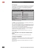
Table 6
represents some of the drinking water guidelines published
by the US EPA. Consult a water treatment adviser in your area to assess your
local needs. Proper water treatment will aid in the longevity of the unit and ensure
maximum efficiencies.
DESCRIPTION
MAX
MIN
Water Pressure
150 psi
40 psi
Programmable water temperature
149°F (65°C)
104°F (40°C)
Minimum Flow Rate to Activate DHW Sensor
N/A
0.5 GPM
Acceptable pH range
8.5 pH
6.5 pH
Total Dissolved Solids
500 mg/L
Total Hardness
200 mg/L 11.68 gr/gal
Aluminum
0.05 to 0.2 mg/L
Chlorides
250 mg/L
Copper
1.0 mg/L
Iron
0.3 mg/L
Manganese
0.05 mg/L
Zinc
5 mg/L
Table 6: Domestic Water Quality Guidelines
1.7.2 Domestic Hot Water Piping
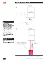
The domestic water piping connections are located at the bottom of the unit,
see
Figure 1b.
The connections are 1/2" male NPT threads. The cold water inlet is on
the right side and the hot water outlet is on the left side.
A pressure relief valve must be installed:
•
With a maximum pressure setting of 150PSI and rated for a minimum capacity
of not less than the rated input of the unit (NOT supplied with the unit) on the
domestic hot water outlet piping within 6" of the unit.
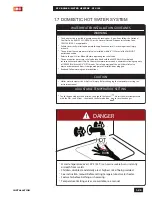
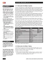
WARNING
HOT WATER CAN SCALD!
Water Temperatures over 125°F
/ 52°C can cause severe burns
instantly or death from scalds.
Children, disabled, and elderly are
at highest risk of being scalded.
•
Never leave them unattended
in or near the shower, bathtub
or sink.
•
Never allow small children to
use a not water faucet or draw
their own bath.
To avoid any potential scald
hazard or if codes require specific
water temperatures at the hot
water faucet, the installer may:
•
Install a field supplied
thermostatic mixing valve at
this appliance and ensure it is
working properly.
AND
•
Set the thermostatic mixing
valve to the lowest temperature
which satisfies your hot water
needs.
TO AVOID INJURY:
•
Feel and adjust water
temperature before bathing or
showering.
•
Water drained from the system
drain valve may be extremely
hot.
•
Make sure all connections are
tight.
•
Direct water flow away from
any person.
WARNINGS
- Bacteria growth can develop
in domestic hot water tanks
and indirect water heaters if the
minimum water temperature is
not set high enough to prevent
its growth.
A potentially hazardous situation,
which can cause serious injury
or death, can exist if the un-used
domestic water connections are
capped off. The unused domestic
water connections are meant to
be left open if not used to allow
for the air in the coil to expand
and contract as the unit is in
operation.
Содержание SFC-199
Страница 46: ...INSTALLATION AND OPERATION INSTRUCTIONS 1 38 SFC BOILER WATER HEATERS SFC 199 PAGE INTENTIONALLY LEFT EMPTY...
Страница 54: ...INSTALLATION AND OPERATION INSTRUCTIONS 2 8 SFC BOILER WATER HEATERS SFC 199 PAGE INTENTIONALLY LEFT EMPTY...
Страница 75: ...6 1 DIAGRAMS SFC BOILER WATER HEATERS SFC 199 6 0 DIAGRAMS 6 1 PARTS DIAGRAMS 6 2 WIRING DIAGRAMS...
Страница 79: ...6 5 DIAGRAMS SFC BOILER WATER HEATERS SFC 199 6 2 WIRING DIAGRAMS Diagram 6 2 1 Pictorial wiring diagram...
Страница 81: ...SERVICE RECORD DATE LICENSED CONTRACTOR DESCRIPTION OF WORK DONE...

