background image


75


7.  Contents of communication signal 


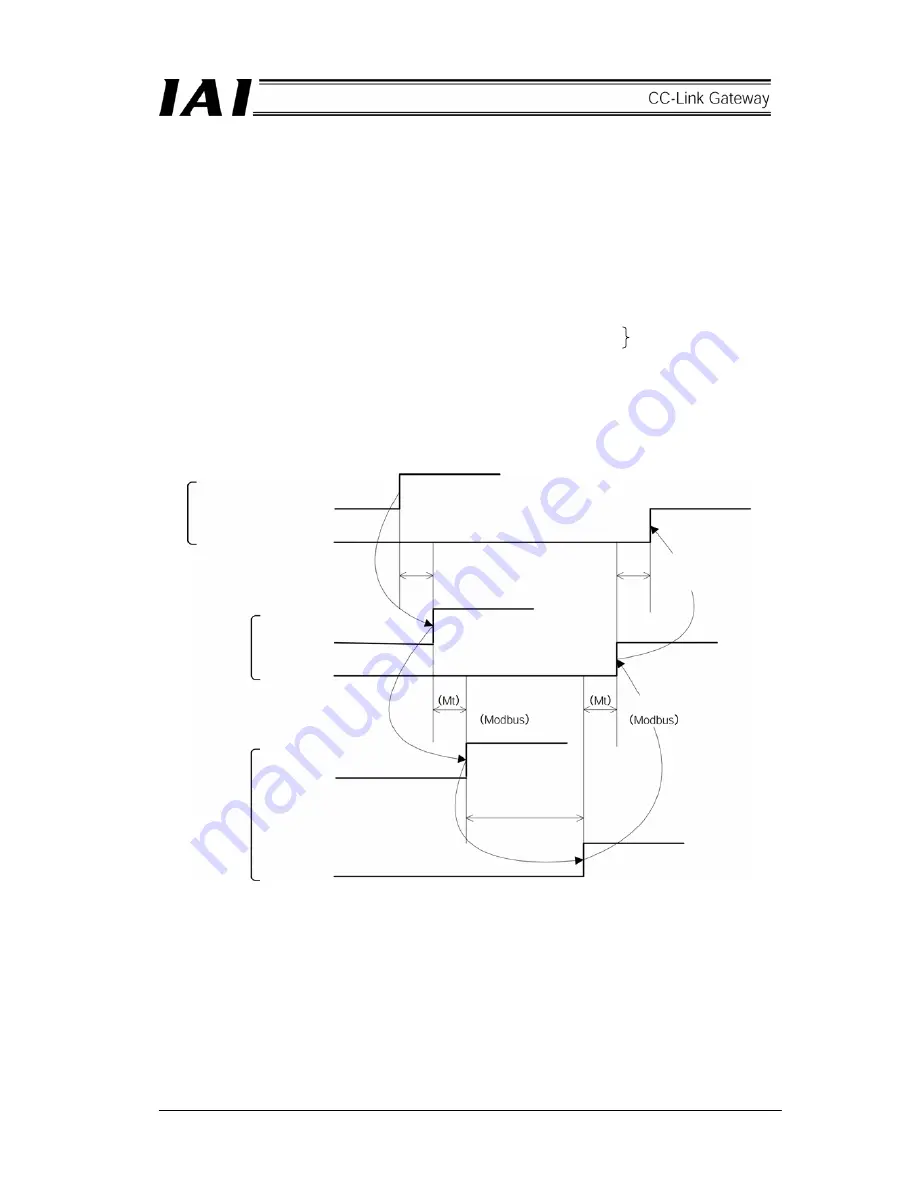
7.1  Outline of timing for communication signal 

 
In order to operate robo-cylinder by the sequence program for the PLC, any of the control signals is turned ON, 
and maximum response time until the response (status) returns to the PLC is expressed by the following 
equation. 
 
Maximum response time (msec) = Yt + Xt + 2 × Mt + Command processing time (such as operating time) 

Mt = 10(msec) 

×

  (n + 1) : SIO link (Modbus) Cycle time 

n :    Number of controlled axes 
Yt : Master station 

  Remote I/O station transmission delay time       

Xt : Remote I/O station 

  Master station transmission delay time 


For Master station 

 Remote I/O station transmission delay time (Yt), Remote I/O station 

 Master 

station transmission delay time, refer to the Operation Manuals for the CC-Link master unit and PLC to be 
mounted. 


(Note)  When communication error is caused due to a problem on the transmission path, communication 

retry (retry times = 3) occurs and a longer SIO link cycle time (Mt) than normal may occur. 


CC-Link transmission 
delay time 

PLC sequence program 

Control signal 


Status signal 

Gateway 

Control signal 


Status signal 

Controler 

Control signal 


Status signal 

Master station 

 Remote I/O 

station 
Transmission delay time (Yt) 

Remote I/O station

 Master 

station 
Transmission delay time (Xt) 

SIO link cycle time


SIO link cycle time


Command 
processing time


Содержание RCM-GW-CC

Страница 1: ...IAI America Inc CC Link RCM GW CC Gateway Unit Operation ManualFirst Edition...

Страница 2: ...tion 17 4 2 Input and output signal of gateway unit 20 4 3 Building of SIO communication network SIO communication 23 5 Outline of CC Link 32 5 1 Data communication 32 5 2 Address assignment of master...

Страница 3: ...98 9 1 Outline of configuration 98 9 2 Actuator operating pattern 99 9 3 Various settings on SIO link side 99 9 4 Setting of gateway unit 101 9 5 Setting on CC Link master side 101 9 6 Address Correl...

Страница 4: ......

Страница 5: ...work Physical standard for SIO communication network is RS 485 and slave addresses on this network are 1 16 All data exchanged between the CC Link and the Modbus protocol communication network are onc...

Страница 6: ...upper network Ethernet is mostly used for this level 3 Controller level This frequently handles real time information for a production line and is referred to as Network between PLCs 4 Field level Th...

Страница 7: ...h CC Link unit is installed communication can be made without a particular program 4 Since line efficiency is high communication with high speed response can be made For details of CC Link refer to Op...

Страница 8: ...Further input and output of various status signals and present position data can be read 2 Push operation mode Push operation can be performed and the maximum connecting axis number totals 3 axes Thi...

Страница 9: ...gnated operation Completed position No reading Connectable axis number 14 14 7 3 16 Settable axis No 1 0 13 0 13 0 6 0 2 0 15 Position data designated maximum value 2 327 67mm Designated to position t...

Страница 10: ...6 1 5 How to identify model RCM GW CC Basic model For CC Link Gateway unit...

Страница 11: ...lf duplex Synchronization system Asynchronous type Transmission path format Equivalent to EIA RS485 2 wire type Communication speed 30 4kbps Error control system No parity bit CRC 3 Communication cabl...

Страница 12: ...8 2 2 External dimension drawing Mounting dimension...

Страница 13: ...5 Controller communication line SDA Communication line SDB Communication line GND Ground FG Frame ground 11 Power supply input connector 6 CC Link communication connector DA Communication line DB Com...

Страница 14: ...on error occurs in communication between the CC Link gateway and controller No response overrun framing error or CRC error Normal T ER Unlit Normal CRC Cyclic Redundancy Check Data error detecting met...

Страница 15: ...osition No designating mode Large 176 176 6 Simple direct value Position No designating mode Middle 136 136 7 Simple direct value Position No designating mode Small 68 68 4 External port switching inp...

Страница 16: ...the next 8 is lit 8 CC Link communication status LED Operating status of the CC Link gateway and network status can be checked by the four LEDs Indicating status Description Lit Normal operation Lit b...

Страница 17: ...communication rate between the CC Link gateway and the controller is fixed to 230 4kbps When the PORT is ON the CC Link communication does not become abnormal however data communication for SIO commun...

Страница 18: ...corrosive or inflammable gasses under a temperature of 0 to 40 C and humidity of 85 or less non condensing d Use the gateway main body where it will not receive any external vibration or shock e Preve...

Страница 19: ...ources can be eliminated by implementing the measures specified below 1 AC solenoid valves magnet switches and relays Measure Install a surge absorber in parallel with the coil 2 DC solenoid valves ma...

Страница 20: ...e gateway unit vertically on a wall as shown below and provide a minimum clearance of 50mm above and below the gateway unit and a minimum clearance of 100mm on the front for wiring For lateral install...

Страница 21: ...ws an example of configuration to build a CC Link by using a gateway unit Host system PLC master station Terminal resistor Slave station Gateway unit Teaching box Terminal resistor 4 direction junctio...

Страница 22: ...18 SIO communication connection is allowed even by multi drop method using terminal blocks as follows Gateway unit Terminal block Terminal resistor...

Страница 23: ...a dedicated shielded 3 core twisted paired cable as a cable The dedicated cable is as follows Color Signal type Blue Communication line A DA White Communication line B DB Yellow Communication ground...

Страница 24: ...ored Connector for teaching box and personal computer Teaching box Teaching box Emergency stop signal output Allowable load voltage 30V DC Allowable load current 1A Port switch Gateway power supply 24...

Страница 25: ...al from the emergency stop pushbutton switch on the teaching box is outputted to the outside while the port is ON this signal can be incorporated into the emergency stop circuit for the whole system E...

Страница 26: ...rent 300mA max Allowable load voltage 30V DC Allowable load current 1A No voltage dry contact input load 24V DC 7mA Set GND ground level to that of controller or ERC actuator to be connected Internall...

Страница 27: ...nnect a terminal resistor at the end A terminal resistor is incorporated into the gateway unit side therefore it is unnecessary to connect it 2 The communication cable should be supplied by customer I...

Страница 28: ...weld the cable press fit housing with the cables inserted from above 5 Heat treat the cable protective tube Pin numbers of e CON connector Be sure to insert the terminal resistor 220 1 4W into the end...

Страница 29: ...ty 1 2 E Con connector Model 4 1473562 4 Manufacturer MP Quantity 1 Compatible wire coating outline 1 35 1 6mm 3 Terminal resistor 220 1 4W with E Con connector Quantity 1 Controller end Mini DIN conn...

Страница 30: ...terminal resistor e CON connector AMP made 4 1473562 4 Green e CON connector AMP made 3 1473562 4 Orange Junction AMP made 3 1473574 4 Recommended brand Taiyo Electric Wire Cable SIO communication ma...

Страница 31: ...owing diagram For details refer to the Operation Manual for the ERC2 controller 4 In the case of a combination of PCON SE ACON SE ERC2 SE and SCON The previous items 2 and 3 are basic connections Perf...

Страница 32: ...ers can be put into an emergency stop status by the emergency stop switch on the teaching box connected to the gateway unit CAUTION 1 The following example shows a wiring path for an emergency signal...

Страница 33: ...2A max one unit Teaching box EMG push button T P connector Gateway unit PCON SE controller EMG reset switch EMG push button Gateway power supply SIO communication SIO connector SIO connector connectio...

Страница 34: ...switch EMG push button Gateway power supply SIO communication SIO connector SIO connector connection detecting circuit Connection detecting signal H Drive stop signal L Time constant Control power sup...

Страница 35: ...1 Open the user adjusting screen 2 Move the cursor to the assignment NO _ with key 3 Enter axis No and press the Return key 4 Enter 2 into adjusting NO _ and press the Return key Operation of simple...

Страница 36: ...automatically communicated between the master station and slave station via this buffer memory regardless of the CPU for the PLC The CPU uses the buffer memory in the master station and the CPU inter...

Страница 37: ...H 2DFH addresses and the remote register RWr is assigned to 2E0 H 3DF H addresses Number of links per one remote station is respectively 32 points 2 words for remote input and output RX RY and 4 point...

Страница 38: ...tic refresh Automatic refresh Automatic refresh 2 words for one station 2 words for one station 2 words for one station 2 words for one station Remote output RY Remote register RWw Remote register RWr...

Страница 39: ...spective two words of word register for input and output It is recommended to use data of this word register on the bit register by performing transmission processing ON OFF control for communication...

Страница 40: ...0 16 of axes used in position No designating mode by 5 bit binary 2 PPS2 1 PPS1 Control signal 0 0 PPS0 Use this in simple direct value position No designating mode In another mode always turn this OF...

Страница 41: ...tting switch 3 ON output 9 MOD2 Mode setting switch 2 ON output 8 MOD1 Mode setting switch 1 ON output This outputs setting status of the mode setting switch 7 Major V 4 6 Major V 2 5 Major V 1 Output...

Страница 42: ...e as shown in the following table Primary functions Direct control Indirect control Ineffective Remarks Home return operation Positioning operation Speed acceleration and deceleration setting This is...

Страница 43: ...ntrol signal 12 RX 6F 60 Status signal 13 Status signal 12 RY 7F 70 Prohibited from use because this is in CC Link system region RX 7F 70 Prohibited from use because this is in CC Link system region O...

Страница 44: ...a designation and present position data are integers with a sign of one word 16 bits and the PLC can handle numeric values of 32 768 to 32 767 unit 1 100mm however set the position data in a range 0 t...

Страница 45: ...When the integer is negative it is indicated by complement of 2 therefore the uppermost bit becomes 1 F 7 EMGS On emergency stop E 6 Cannot be used D 5 PWR Controller preparation completion C 4 SV Ope...

Страница 46: ...rimary functions controllable in this mode are as shown in the following table Primary functions Direct control Indirect control Ineffective Remarks Home return operation Positioning operation This op...

Страница 47: ...6F 60 Status signal 13 Status signal 12 RY 7F 70 Prohibited to use because this is in CC Link system region RX 7F 70 Prohibited to use because this is in CC Link system region Output writing Register...

Страница 48: ...N OFF signals in bit units Command position No and completed position No are handled in binary data of one byte 8 bits Set the command position No in a range of position number set by the controller f...

Страница 49: ...ng is Hex0F21 F 7 EMGS On emergency stop E 6 Cannot be used D 5 PWR Controller preparation completion C 4 SV Operation preparation completion Servo on status B 3 MOVE On moving A 2 HEND Home return co...

Страница 50: ...information data abnormality A3 7 Excitation detection error B8 Operation time time out in home return operation BE 8 Actual speed excessively large C0 9 Overvoltage C9 Overheat CA Control power volt...

Страница 51: ...ve command by adding or subtracting data of same moving amount to from the present position by host PLC Push operation Speed change during movement Speed data is accepted at start of positioning There...

Страница 52: ...ion designation 11 Control signal 10 RX 5F 50 Cannot be used Status signal 5 RY 6F 60 Acceleration and deceleration designation 13 Control signal 12 RX 6F 60 Cannot be used Status signal 6 RY 7F 70 Pr...

Страница 53: ...handle numeric values of 32 768 to 32 767 Set the acceleration and deceleration and speed in a range of specification of the actuator and set position data in a range of soft stroke 1 word 16 bits PLC...

Страница 54: ...command 2 HOME Home return command 1 CSTR Start command Control signal 0 RES Reset command Speed designation 16 bit data 16 bit integer Unit 0 01mm sec Set command speed in hexadecimal number Example...

Страница 55: ...moving 2 HEND Home return completion 1 PEND Positioning completion Status signal 0 ALM Alarm occurring PLC input Present position data 16 bit data 16 bit integer with sign Unit 0 01mm Set position dat...

Страница 56: ...not be directly processed Give command by adding or subtracting data of same moving amount to from the present position by host PLC Push operation Speed change during movement Speed data is accepted a...

Страница 57: ...Y 6F 60 Cannot be used RX 6F 60 Cannot be used RY 7F 70 Prohibited from use because this is in CC Link system region RX 7F 70 Prohibited from use because this is in CC Link system region Output writin...

Страница 58: ...performing transmission processing Set current limit value acceleration and deceleration and speed in a range of the specification of the actuator and set position data in a range of the soft stroke...

Страница 59: ...put is handled as a negative number when the uppermost bit is 1 However note that the data is handled as normal numeric data on the PLC PLC input 1 word 16 bits Position data designation Present posit...

Страница 60: ...setting to 50 set it as FFH50 255 50 127 decimal 7FH Speed designation 24bit data 24 bit integer unit 0 01mm sec Set command speed in hexadecimal number Example In the case of 200mm sec the data is 00...

Страница 61: ...tion C b 12 SON Servo on command B b 11 STP Pause command A b 10 HOME Home return command 9 b9 CSTR Start command PLC output Control signal 8 b8 RES Reset command F 8 b15 8 Cannot be used 7 b7 EMGS On...

Страница 62: ...d not used for Ver 100 and Ver 1 10 Primary controllable functions are as shown in the following table Primary functions Position No designated axis Simple direct value axis Remarks Home return operat...

Страница 63: ...e axis is assigned They cannot be alternately assigned Size of input and output region of overall gateway is determined by the mode setting switch SW1 as shown in the following table SW1 Overall input...

Страница 64: ...Data 5 Reserve Gateway control signal 0 Gateway control signal 1 Response command Data 0 Data 1 Data 2 Data 3 Data 4 Reserve Data 5 Reserve Fixed region 10 word 20 word 24 word 64 word 48 word 24 word...

Страница 65: ...designated axis Pattern 0 Standard Pattern 1 Teach Pattern 2 Positioning 256 points Pattern 3 Positioning 512 points Pattern 4 Air cylinder PLC output RWw PLC input RWr Pattern 0 Pattern 1 Pattern 2...

Страница 66: ...o PLC output Command position No b6 b0 ST0 ST6 4 Start position is designated by bit pattern b15 BALM 0 4 Battery voltage drop alarm b14 ALM 0 4 Alarm occurring b13 EMGS 0 4 On emergency stop b12 SV 0...

Страница 67: ...bit integer with the sign in units of 0 01mm PLC output Control signal m is a head address assigned as simple direct value axis n is a number of simple direct designated axis Position data designatio...

Страница 68: ...ommand b11 STP Pause command b10 HOME Home return command b9 CSTR Start command b8 RES Reset command PLC output Control signal b7 b0 Cannot be used Present position data 32 bit data This is a 32 bit i...

Страница 69: ...nation Position table PLC numeric value designation PLC numeric value designation PLC numeric value designation Position table Speed Parameter Position table Parameter PLC numeric value designation Pa...

Страница 70: ...side write 1004H Individual zone boundary side write 1005H Acceleration write 1006H Deceleration write 1007H Current limit value write at push Position table data write 1008H Load current threshold v...

Страница 71: ...s request at normal 2 1002H 3 Position No 4 5 Speed data 24 bit integer 6 Axis No 0 to FH 7 0 Speed write 8 0 Same value as request at normal 2 1003H 3 Position No 4 5 Position data 24 bit integer wit...

Страница 72: ...3 Position No 4 0000 to 00FFH 00FFH Maximum current 5 0 6 Axis No 0 to FH 7 0 Current limit value write at push 2 8 0 Same value as request at normal 2 1008H 3 Position No 4 0000 to 00FFH 00FFH Maximu...

Страница 73: ...me value as request at normal 4 0 5 0 Speed data 3 6 Axis No 0 to FH 7 0 Speed read 8 0 Same value as request at normal 2 1043H 3 Position No Same value as request at normal 4 0 5 0 Individual zone bo...

Страница 74: ...4 0 0000 00FFH 00FFH Max current 5 0 6 Axis No 0 to FH 7 0 Current limit value read at push 5 8 0 Same value as request at normal 2 1048H 3 Position No Same value as request at normal 4 0 0000 00FFH...

Страница 75: ...normal 4 0 00FFH Now recording on ROM 0000H Recording on ROM completed 5 0 6 Axis No 0 to FH 7 0 Position table data ROM writing completion coil read 8 0 Same value as request at normal 4 Presently oc...

Страница 76: ...for every axis in process of movement by this command movement by this command is cancelled and operation is performed by the latest movement command Note that each axis has two movement command inter...

Страница 77: ...Invalid axis No 1 0102H Invalid position No 1 0103H Invalid request command 1 0201H Communication fault 0202H Controller execution impossible 1 If data from the PLC is checked and this is found an err...

Страница 78: ...74...

Страница 79: ...on transmission delay time For Master station Remote I O station transmission delay time Yt Remote I O station Master station transmission delay time refer to the Operation Manuals for the CC Link mas...

Страница 80: ...he emergency stop status is released 3 Alarm ALM This signal is turned ON when the protecting circuit function for the controller detects any abnormality Function This signal is turned ON when the pro...

Страница 81: ...ng signal is OFF The target position data is transmitted to the controller at ON edge of the CSTR at signal startup 3 The PEND is turned OFF after the CSTR is ON and after tdpf 4 Turn OFF the CSTR by...

Страница 82: ...78 Position data measurement value Present position 1 2 3 4 4 5 6 7...

Страница 83: ...the CSTR start at startup of signal 3 It is possible to change the acceleration and deceleration and speed data during movement To change the acceleration and deceleration or speed during movement tur...

Страница 84: ...80 Speed acceleration and deceleration set value Actuator speed Speed n2 Speed n3 1 2 3...

Страница 85: ...in home return reverse direction with the DIR signal ON and in home return direction with the DIR signal OFF 7 Turn ON the CSTR start after that 0 Turn ON the CSTR in a status that the PEND Positionin...

Страница 86: ...82 Position data set value Speed acceleration and deceleration set value Positioning width value set value Current limit value set value Present position 1 2 3 4 5 6 7 8 9 10 11 12 13...

Страница 87: ...nuals for PCON ACON SCON and ERC2 1 Set a position No to the command position No register 2 Turn ON the CSTR start after that 0 3 The PEND positioning completed is turned OFF after the CSTR is turned...

Страница 88: ...84 Command position No Completion position No 1 2 3 4 5 6...

Страница 89: ...to an operable status When the servo is turned on the LED green for SV on the front of the controller is lit In ERC2 the LED on the upper part of the motor unit is lit in green The SV operation prepar...

Страница 90: ...absolute position moving command in home return non completion status in cases other than the position No designated mode 11 Zone ZONE1 ZONE2 In the case of the position No designated mode zone signa...

Страница 91: ...87...

Страница 92: ...ay detects that the request command became other than zero then transmits the request data to the applicable axis 3 The gateway receives a response from the applicable axis then outputs the response r...

Страница 93: ...89...

Страница 94: ...tting for controller It is necessary to set as follows in order to make the controller communicate with the gateway unit 1 Set so as not to duplicate axis No Note that a range of settable axis No depe...

Страница 95: ...osition data limit designated mode 14 axes 4 1 time Position No designated mode 14 axes 4 1 time Normal positioning mode 7 axes 4 1 time Push operating mode 3 axes 3 2 times example Simple direct valu...

Страница 96: ...gnation POS designation Direct value speed acceleration and deceleration designation Direct value speed acceleration and deceleration positioning width push Simple direct value Position No designation...

Страница 97: ...ntrolled axes Position data limit designation 8 word 16 word 4 14 Position No designation 8 word 16 word 4 14 Normal position data designation 8 word 16 word 4 7 Push operation data designation 8 word...

Страница 98: ...t RX For station No 1 For station No 2 For station No 3 For station No 4 For station No 5 For station No 6 For station No 7 For station No 8 For station No 9 Output 2 Master station Gateway unit Maste...

Страница 99: ...ation Station No 1 Exclusive one station Gateway unit RCM GW CC Station No 2 Exclusive four stations Buffer address Remote register RWr For station No 1 For station No 2 For station No 3 For station N...

Страница 100: ...ation No 1 Exclusive one station Gateway unit RCM GW CC Station No 2 Exclusive four stations Buffer address Remote register RWw For station No 1 For station No 2 For station No 3 For station No 4 For...

Страница 101: ...ork parameter setting Website http www iai robot co jp To download it open the File for field network setting from the Download Support menu on the website to select the CSP file For how to set the re...

Страница 102: ...ng completed Operation preparation completed Servo on Operation Alarm Pause Emergency stop release Indication lamp Remote I O Input 8 points Output 8 points PCON CY controller Gateway unit Station No...

Страница 103: ...tting 4 Click the Axis No assignment N 5 Axis No assignment table appears then set No 6 Click the OK then ESC 7 Connect and disconnect the SIO link cable to set the next axis No 8 When ended finally c...

Страница 104: ...6 Exit the personal computer supporting software 7 Disconnect the personal computer cable from the gateway unit and turn OFF the port switch CAUTION After connecting the personal computer supporting...

Страница 105: ...meters setting to build a network 9 5 1 Hardware setting Station No setting is as follows in this operational example Station No 0 Station No 1 Station No 2 Station No 3 Station No 4 Station No 5 1 St...

Страница 106: ...munication retry times and station information etc Automatic refresh parameters These parameters are for automatically refreshing master station buffer memory such as RX RY and PLC CPU device such as...

Страница 107: ...m from the project data list and network parameter select dialog box appears then click the CC Link button 2 Network parameter setting screen for CC Link appears then set the unit sheet number to one...

Страница 108: ...e as follows Start I O No I O address of master unit 0080 All connect account Number of remote stations 2 Remote input RX Refresh device X100 Remote output RY Y100 Remote register RWr D200 Remote regi...

Страница 109: ...s then click the End button at the lower part of the screen The station No 1 is the gateway unit and is used in the position No designated mode therefore it becomes the remote device station exclusive...

Страница 110: ...2 into the PLC 1 Transfer setup Click the Online O Transfer setup C menu then the following transfer setup designated screen appears I F PC side Serial USB I F PLC side PLC module Other station No sp...

Страница 111: ...PLC write screen and select the MAIN for program and the PC Network for parameter Click Execute button then write is performed and when it is completed dialog box for confirmation appears Click OK Cl...

Страница 112: ...al Status signal Status signal Status signal Status signal Status signal Status signal Status signal Status signal Prohibited to use because this is CC Link system region PLC output Gateway unit Each...

Страница 113: ...nput Read Register Word register Completion position Zone signal Cannot be used Gateway status signal 0 Gateway status signal 1 Completion position Zone signal Completion position Zone signal Completi...

Страница 114: ...s 1 which are DeviceNet slave axes is as follows Insides of parentheses are SIO link axis Nos Gateway unit normal SIO link axis designation SIO link start Axes 0 1 PWR check Turn on servo for axes 0 1...

Страница 115: ...111 Command P No 1 to axes 0 1 Set CSTR to 1 Set CSTR to 0 Positioning completed One second timer 2 1...

Страница 116: ...ady Master data link Station No normal Station No normal Remote I O input 1 Remote I O input 2 Remote I O output 1 Remote I O output 2 Gateway Gateway Gateway GW control signal 1 GW control signal 1 G...

Страница 117: ...113 No 2 Axis 0 Operation lamp Axis 0 PWR No 2 Axis 0 Servo on lamp Axis 0 Servo on Axis 0 SV Axis 0 HEN Axis 0 Servo on No 2 Axis 0 SRDY lamp No 2 Axis 0 Home return completed Axis 0 Operation flag...

Страница 118: ...xis command position No Axis command position No Axis command position No Axis command position No Axis 0 MOVE Axis 0 PEND Axis 0 PO start flag Flag Flag Axis 0 CSTR Axis 0 PEND Completion P No Comple...

Страница 119: ...0 MOVE Axis 0 P1 setting flag Axis command position No Axis 0 P1 setting flag Axis 0 P1 setting flag Axis command position No Axis command position No Axis command position No Axis command position No...

Страница 120: ...Axis 0 CSTR Axis 0 P1 completion Axis 0 P0 start flag Axis 0 P1 start flag Axis 0 P0 completion Axis 0 P1 completion No 2 Axis 0 positioning completed lamp No 2 Axis 0 pause Axis 0 pause pushbutton Ax...

Страница 121: ...xis 0 STP No 3 Axis 1 operation lamp Axis 1 ALM Emergency stop No 3 Axis 1 operation lamp Axis 1 PWR No 3 Axis 1 servo on lamp Axis 1 servo on No 3 Axis 1 SRDY lamp No 3 Axis 1 home return completed A...

Страница 122: ...ommand position No Axis command position No Axis command position No Axis command position No 1 second Axis 1 MOVE Axis 1 PEND Axis 1 P0 start flag Flag Axis 1 CSTR Flag Axis 1 PEND Completion P No Co...

Страница 123: ...1 MOVE Axis 1 P1 setting flag Axis 1 P1 setting flag Axis 1 P1 setting flag Axis command position No Axis command position No Axis command position No Axis command position No Axis command position No...

Страница 124: ...tion Axis 1 P1 completion 1 second Axis 1 P1 start flag Axis 1 P0 completion Axis 1 P1 completion flag No 3 Axis 1 positioning completion lamp No 3 Axis 1 pause No 3 Axis 1 pause button No 3 Axis 1 pa...

Страница 125: ...121 No 3 Axis 1 pause No 3 Axis 1 pause lamp No 3 Axis 1 STP...

Страница 126: ...the power and disconnect the cables f Check the noise elimination measures grounding installation of surge killer etc g Check the operation by the teaching box or personal computer software Connect t...

Страница 127: ...way status indication LED is lit Further communication status can also be checked by the TxD Green and RxD Green on the LED For details refer to the item of 2 SIO communication status LED in 2 3 Name...

Страница 128: ...Check the communication status LED and check the following depending on each status 1 Check if wiring for the communication line is correctly connected 2 Check if the gateway unit is correctly set to...

Страница 129: ...ed to local station Impossible status Polling response is performed but refresh reception is CRC error Impossible status Data to local station is CRC error Impossible status Not link started Impossibl...

Страница 130: ...126...

Страница 131: ......

Страница 132: ...7 South Main St Suite F Marlboro NJ 07746 TEL 732 683 9101 FAX 732 683 9103 Home page www intelligentactuator com IAI Industrieroboter GmbH Ober der R th 4 D 65824 Schwalbach am Taunus Germany TEL 061...

Отзывы: