


15
b. Precautions regarding wiring method
Separate the communication lines for the gateway unit and the wiring for the CC-Link
communication line from high-power lines such as a cable connecting to a power circuit. (Do not
bundle together wiring for the communication lines with high-power lines or place them in the same
cable duct.)
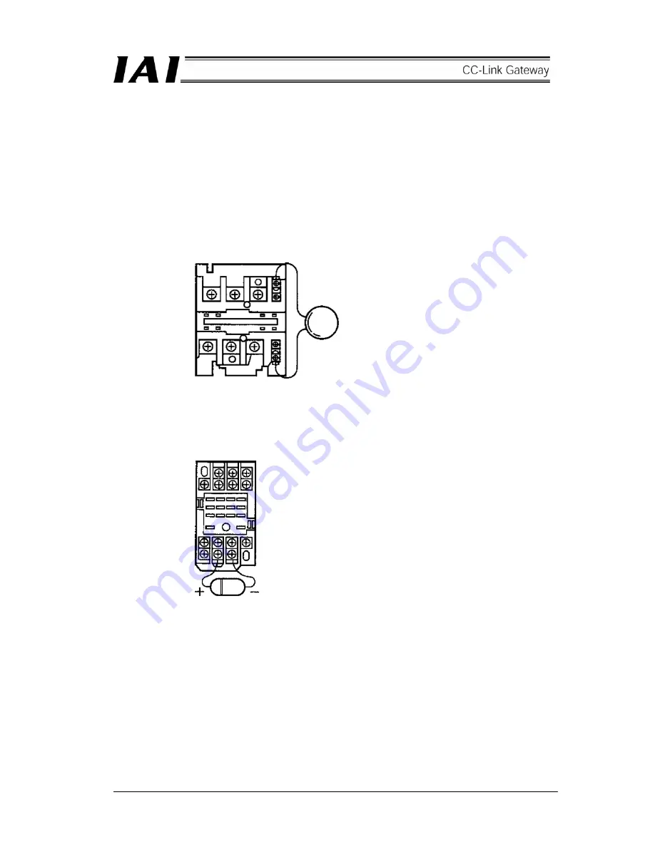
c. Noise sources and elimination
Among the numerous noise sources, solenoid valves, magnet switches and relays are of particular
concern when building up a system. Noise from these sources can be eliminated by implementing
the measures specified below.
[1] AC solenoid valves, magnet switches and relays
Measure: Install a surge absorber in parallel with the coil.
[2] DC solenoid valves, magnet switches and relays
Measure: Install a diode in parallel with the coil. Determine the diode capacity in accordance
with the load capacity.
←
Point
Install a surge absorber to each
coil over a minimum wiring
length. Installing a surge
absorber to the terminal block or
other part will be less effective
because of a longer distance
from the coil.
In a DC circuit, connecting a diode in reverse polarity
will damage the diode, internal parts of the controller
and/or DC power supply, so exercise sufficient caution.
Содержание RCM-GW-CC
Страница 1: ...IAI America Inc CC Link RCM GW CC Gateway Unit Operation ManualFirst Edition...
Страница 4: ......
Страница 10: ...6 1 5 How to identify model RCM GW CC Basic model For CC Link Gateway unit...
Страница 12: ...8 2 2 External dimension drawing Mounting dimension...
Страница 78: ...74...
Страница 82: ...78 Position data measurement value Present position 1 2 3 4 4 5 6 7...
Страница 84: ...80 Speed acceleration and deceleration set value Actuator speed Speed n2 Speed n3 1 2 3...
Страница 88: ...84 Command position No Completion position No 1 2 3 4 5 6...
Страница 91: ...87...
Страница 93: ...89...
Страница 115: ...111 Command P No 1 to axes 0 1 Set CSTR to 1 Set CSTR to 0 Positioning completed One second timer 2 1...
Страница 125: ...121 No 3 Axis 1 pause No 3 Axis 1 pause lamp No 3 Axis 1 STP...
Страница 130: ...126...
Страница 131: ......


