


61
6.6.2 Assignment for each axis
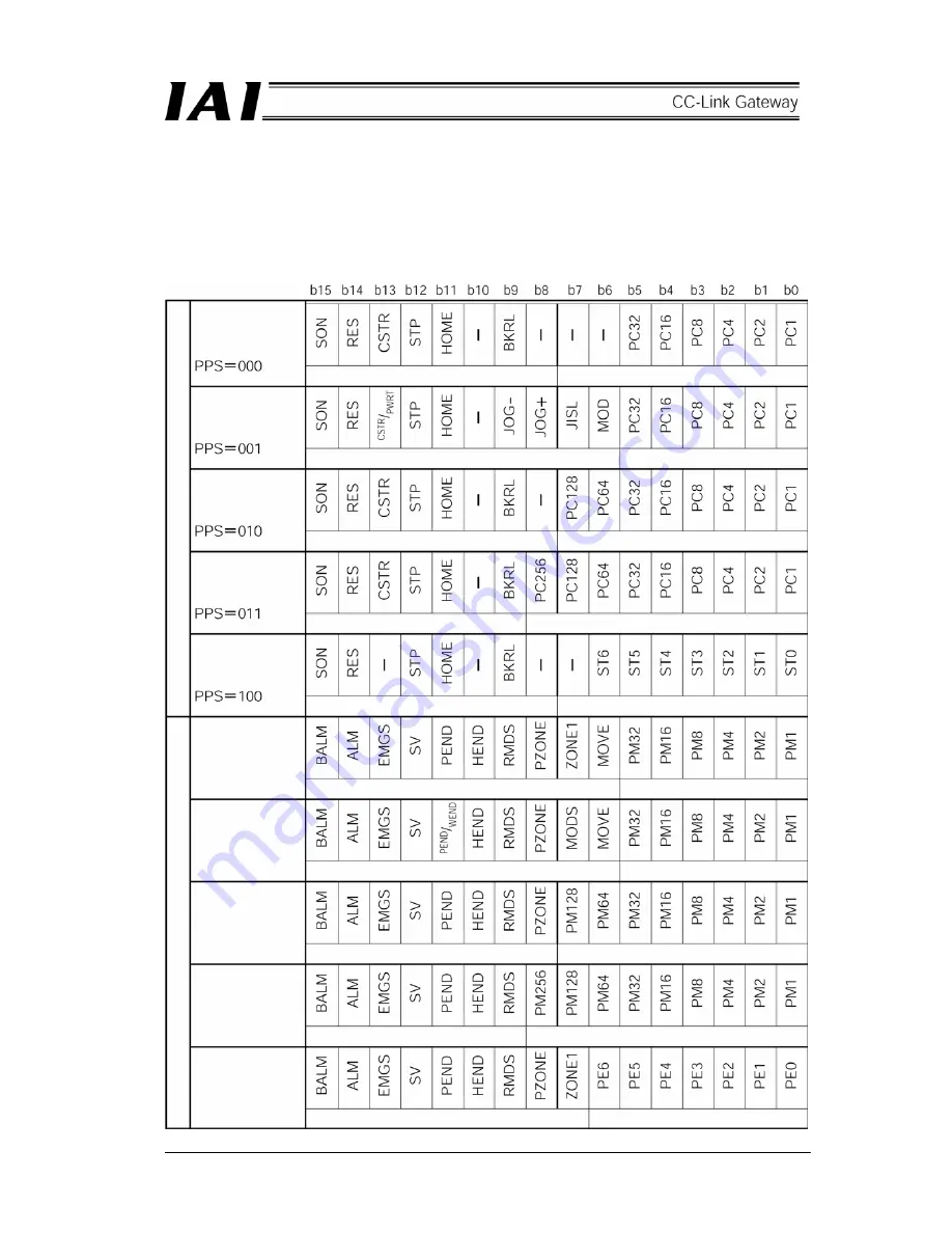
Input and output signals for each axis position No. designated mode and those in simple direct value
mode are different from each other in size of region and its content. Further, in the position No.
designated mode, meaning of each bit depends on the pattern set by gateway control signal PPS.
(1) Control signal and status signal of position No. designated axis
Pattern 0
(Standard)
Pattern 1
(Teach)
Pattern 2
(Positioning 256
points)
Pattern 3
(Positioning 512
points)
Pattern 4
(Air cylinder)
PLC
outp
ut R
W
w
PLC
in
put R
W
r
Pattern 0
Pattern 1
Pattern 2
Pattern 3
Pattern 4
Control signal
Command position No.
Control signal
Command position No.
Control signal
Command position No.
Control signal
Command position No.
Control signal
Start position No.
Status signal
Completed position No.
Status signal
Completed position No.
Status signal
Completed position No.
Completed position No.
Status signal
Completed position No.
Status signal
Содержание RCM-GW-CC
Страница 1: ...IAI America Inc CC Link RCM GW CC Gateway Unit Operation ManualFirst Edition...
Страница 4: ......
Страница 10: ...6 1 5 How to identify model RCM GW CC Basic model For CC Link Gateway unit...
Страница 12: ...8 2 2 External dimension drawing Mounting dimension...
Страница 78: ...74...
Страница 82: ...78 Position data measurement value Present position 1 2 3 4 4 5 6 7...
Страница 84: ...80 Speed acceleration and deceleration set value Actuator speed Speed n2 Speed n3 1 2 3...
Страница 88: ...84 Command position No Completion position No 1 2 3 4 5 6...
Страница 91: ...87...
Страница 93: ...89...
Страница 115: ...111 Command P No 1 to axes 0 1 Set CSTR to 1 Set CSTR to 0 Positioning completed One second timer 2 1...
Страница 125: ...121 No 3 Axis 1 pause No 3 Axis 1 pause lamp No 3 Axis 1 STP...
Страница 130: ...126...
Страница 131: ......