


4. Operation Program
38
4.3. Electronic Shaft
Synchronizes to the specified master axis, and it is a function that slave axis follows the
specified gear ratio.
Movement amount of slave axis is calculated by the formula below.
Gear Ratio Numerator
Slave Axis Movement Amount = Master Axis Movement Amount x
Gear Ratio Denominator
The gear ratio numerator can be specified in the range from -9999999 to -1 or 1 to 9999999
and the denominator from 1 to 9999999. If a negative value is specified to the gear ratio
numerator, slave axes movement is in the direction opposite to the master axis. This operation
is enabled using the XSFS command. [Refer to the explanation of the XSFS command in
Chapter 3 “Programs.”]
•
The synchronizing control in this feature is just a function to perform synchronization in
operation command level, and is not a function to perform synchronizing operation based on
the relations of the actual positions of each axis or the actual torque. Therefore, if each
synchronizing axis gets linked rigidly with the other, slight difference in position of each axis or
balance in force of each axis may cause an error such as the overload error or deviation
overflow error. Consider having a floating structure or equivalent when the synchronizing
operation axes are required to be linked in order to have a margin to release force.
•
Even when operating axes in the same model code in the gear ration 1 : 1 via an electronic
shaft, each axes should have slight physical difference in position due to variation in installation
position and individual difference of each axis. If it is required to adjust such difference, there is
a way to adjust it by change the gear ratio slightly when executing XSFS Command on the
applicable axis. ([Example] Gear ratio 1 : 1
→
Gear ratio 1000 : 999)
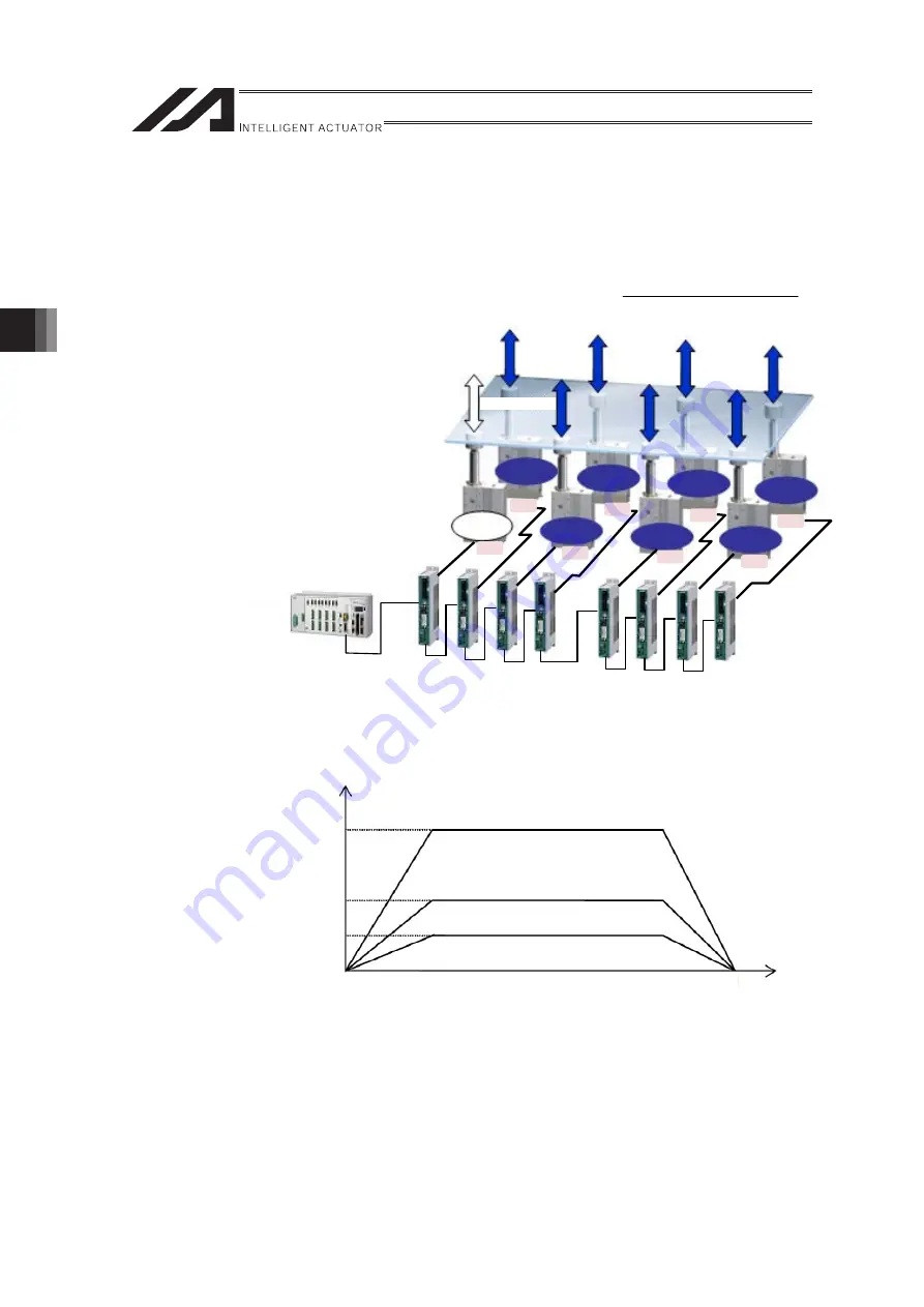
What is the electronic shaft
function?
This function causes a
“slave axis”
to
synchronize with a
“master axis”
at a
specified gear ratio.
If the gear ratio is 1 : 1, all slave axes
perform the same movement as the
main axis as shown in the figure to
the right.
No.1
Master
axis
Slave
axis
Slave
axis
Slave
axis
Slave
axis
Slave
axis
Slave
axis
Slave
axis
X1 (gear ratio) =
XSEL
No.3
No.5
No.7
No.0
No.2
No.4
No.6
Speed
Slave axis (gear ratio 2:1)
Master axis
Slave axis (gear ratio 1:2)
Time
Vm × 2
Vm
Vm × 1/2
ME0364-2B
Содержание RA Series
Страница 2: ......
Страница 4: ...ME0364 2B ...
Страница 22: ...1 Outline of Extension Motion Control Feature 14 ME0364 2B ...
Страница 40: ...3 Basic Settings 32 ME0364 2B ...
Страница 150: ...5 Practical Settings 142 ME0364 2B ...
Страница 170: ...6 Parameter Detail 162 ME0364 2B ...
Страница 174: ...7 Details of Features 166 ME0364 2B ...
Страница 184: ......
Страница 185: ......


