


5. Practical Settings
124
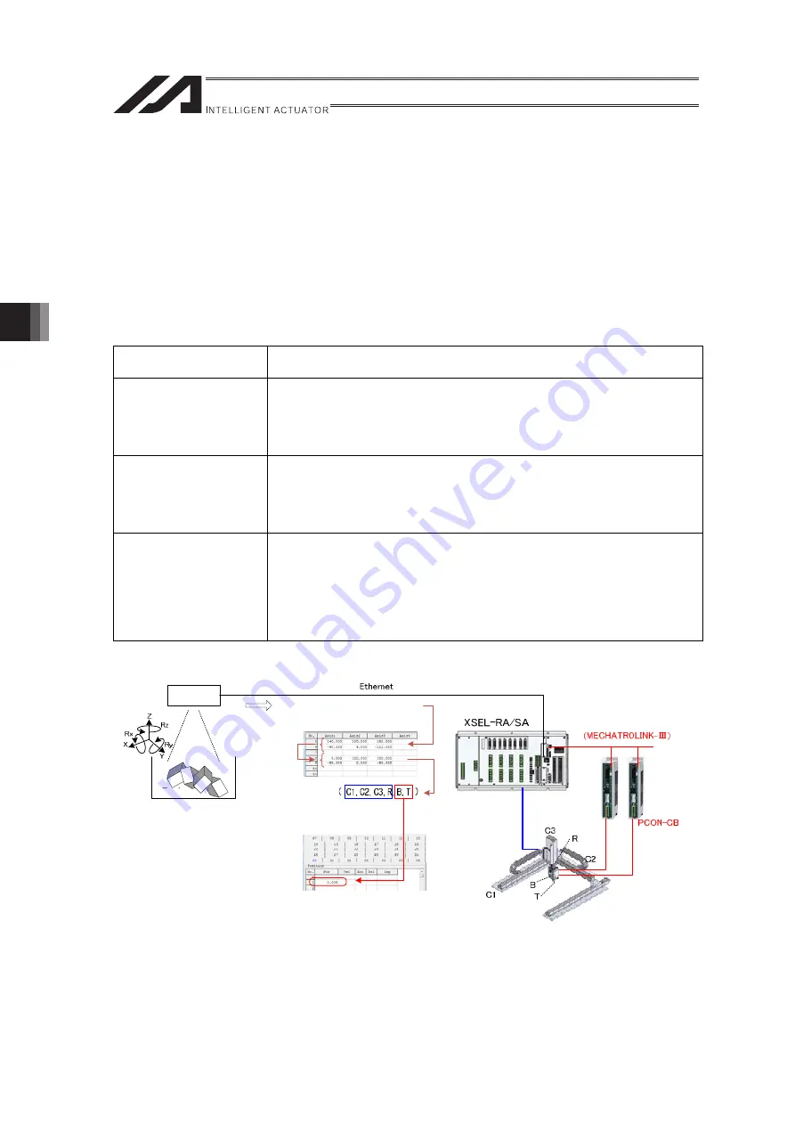
5.3.4. When Operating with Information of Cartesian Coordinates Gained from
Camera
[1] Overview
As the wrist unit operating with PCON and MCON is to be operated with the extension motion, it is
necessary to set the position to the extension motion control axis position data in each axis
coordinate system.
In order to operate a robot equipped with the wrist unit which is combined with the cartesian robot on
the cartesian coordinate system position (X, Y, Z, Rx, Ry and Rz) acquired by a 3D vision sensor, it
is necessary to convert to each axis coordinate system (C1, C2, C3, R, B and T).
Therefore, it is required to convert the coordinates with the coordinate conversion command below.
Example of Use of Coordinate Conversion
Coordinate Converting
Operation
Example of Use
Conversion from Each
Axis Coordinates to
Work Coordinates
During calibration of the 3D vision sensor, convert the current position
expressed in each axis coordinate system (C1, C2, C3, R, B and T) into
the cartesian coordinate system (X, Y, Z, Rx, Ry and Rz) and set it to
the 3D vision sensor (teach robot coordinates in cartesian coordinate
system).
Conversion from Work
Coordinates to Each
Axis Coordinates
During picking of bulk loading using the 3D vision sensor, move to the
workpiece position with MOVP/XMVP Commands by converting the
workpiece position expressed in the cartesian coordinate system
acquired by the 3D vision sensor (X, Y, Z, Rx, Ry and Rz) into each axis
coordinate system (C1, C2, C3, R, B and T).
Conversion from Tool
Coordinates to Work
Coordinates
During picking of bulk loading using the 3D vision sensor, acquire the
approaching / escaping position towards / against the workpiece
position by converting the tool coordinates offset in the tool direction
with the workpiece position expressed in the cartesian coordinate
system acquired by the 3D vision sensor (X, Y, Z, Rx, Ry and Rz) as the
datum of the tool coordinate system (0, 0, 0, 0, 0, 0) into the work
coordinate system.
Extension Motion Control
Standard Motion
Control
(Direct Connect)
•
Cartesian Axis
•
ZR-Axis
(AC Servomotor)
•
Wrist Unit
(Pulse Motor)
Cartesian Coordinate System
(X, Y, Z, Rx, Ry, Rz)
Position Data (Standard)
Coordinate Change
Command
3D Vision
Work
Each Axes Coordinate
System
Positioning
with MOVP
Position Data (Extension)
Positioning with XMVP
ME0364-2B
Содержание RA Series
Страница 2: ......
Страница 4: ...ME0364 2B ...
Страница 22: ...1 Outline of Extension Motion Control Feature 14 ME0364 2B ...
Страница 40: ...3 Basic Settings 32 ME0364 2B ...
Страница 150: ...5 Practical Settings 142 ME0364 2B ...
Страница 170: ...6 Parameter Detail 162 ME0364 2B ...
Страница 174: ...7 Details of Features 166 ME0364 2B ...
Страница 184: ......
Страница 185: ......


