HT4001
Instruction Manual
7-17
MAINTENANCE
Problem
Possible Causes and Solutions
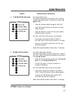
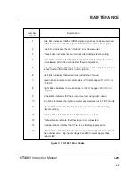
11. Gases and/or water continue to
flow.
12. The POWER DC indicator
is illuminated, but there is no
high frequency and no pilot arc.
11.1.
One or more valves not closing.
All valves should close when in RUN mode (except SV1 if in
N2 mode). Check wiring using the system wiring diagram as
reference to troubleshoot.
12.1.
There is no spark between the spark gap electrodes.
(Spark gap assembly is located in the RHF console)
Clean (with emery cloth), align, and/or re-gap (.020" per gap)
the electrodes, if necessary. Ensure that the electrode
surfaces between the gaps are flat. If surfaces are rounded,
replace and re-gap.
•
Visually inspect the high voltage transformer T1 in the
RHF console for leaking oil or overheating. See
Figure 6-8 for location of T1. Replace T1 if leaking or
overheating.
•
Check for 120VAC at T1 after START command
is given. Note that door interlock switches S1 and S2
have to be closed in order to pass the START sequence.
Switch will close in both IN position, and if pulled OUT.
•
If there is no 120VAC at T1, use wiring diagrams
and check pins, connectors and associated wiring
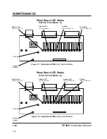
from T1 to relay board PCB4 (see Figure 7-4 for detail of
PCB4). If connections are OK, there may be a problem
with relay PCB4 or control board PCB2.
•
If there is 120VAC at T1, shut down system and
remove capacitors C5A and C5B in RHF console.
Restart system and see if a faint spark is now observed
across the gaps.
•
If a spark is not observed at the gaps, replace T1.
If there is a spark, shut down system, and replace
capacitors C5A and C5B.
(Always replace the
capacitors in pairs).
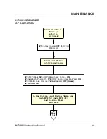
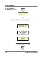
Select RUN
(with S2 on Gas Console)
Activate Plasma START
11-96
Содержание HT4001
Страница 1: ...Plasma Arc Cutting System Instruction Manual 802000 Revision 15 HT4001 EN50199 EN60974 1 ...
Страница 142: ...PARTS LIST 6 6 HT4001 Instruction Manual Figure 6 2 HT4001 Power Supply Inside Front Panel 1a 1b 1c 1d 2 99 2 ...
Страница 148: ...PARTS LIST 6 12 HT4001 Instruction Manual Figure 6 5 HT4001 Power Supply Inside Floor 1 2 3b 3a 3c 3d ...
Страница 152: ...PARTS LIST 6 16 HT4001 Instruction Manual Figure 6 7 HT4001 Power Supply Rear Wall Outside 1 2 6 8 7 4 5 9 3 10 6 95 ...
Страница 239: ...e 2 ...
Страница 240: ...e 3 ...
Страница 241: ...e 4 ...
Страница 242: ...e 5 ...
Страница 244: ...e 7 ...
Страница 245: ...e 8 ...
Страница 246: ...e 9 ...
Страница 247: ...e 10 ...
Страница 257: ...KY ...
Страница 258: ...KY ...
Страница 259: ...KY ...
Страница 260: ...KY ...
Страница 261: ...KY ...
Страница 262: ...KY ...
Страница 263: ...KY ...
Страница 264: ...KY ...
Страница 268: ...KY ...
Страница 269: ...KY ...
Страница 270: ...KY ...

