OPERATION
5-9
HT4001 Instruction Manual
3.
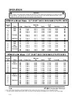
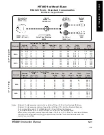
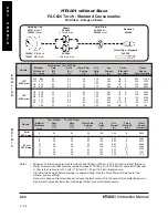
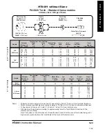
Verify that the proper consumables are installed in the torch. Refer to the
Cut Charts to choose the correct consumables for your cutting needs. See also
Changing Consumable Parts later in this section.
4.
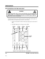
Turn the required supply gas ON.
Set the pressure on the nitrogen supply to read 150 psi +/- 10 psi (10.3 bar
+/- 0.7 bar) at the N
2
pressure gauge on the gas console.
Set the pressure on the oxygen supply to read 120 psi +/- 10 psi (8.3 bar
+/- 0.7 bar) at the O
2
pressure gauge on the gas console.
5.
Turn the water supply to the water chiller ON.
6.
Set the main disconnect switch for the water chiller to the ON position and
depress the START switch on the water chiller. Outlet water pressure should
read between 175-185 psi (12-12.8 bar) on the water chiller gauge. See IM241
Water Chiller Model D instruction manual for adjustment procedure, if necessary.
7.
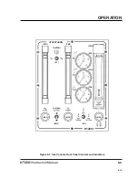
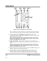
Set S1 on the gas console to plasma gas N
2
or O
2
.
8.
Set the main disconnect switch for the power supply to ON and throw the
POWER circuit breaker on the rear of the power supply to the UP position.
Verify that the POWER AC indicator illuminates.
9.
Set the VOLTAGE and CURRENT on the DR V/C module. Select the arc current
and voltage from the
Cut Charts for the type and thickness of metal to test cut.
Notes: •
If using the H-401 power supply as a slave and you need to reduce the
existing arc current level, lower the current to below 360A on the remote
V/C before resetting to the desired value.
•
If using the H-401 power supply as a slave, note that the current control
adjust knob on the front of the H-401 supply will have no effect on setting
current for the slave.
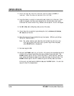
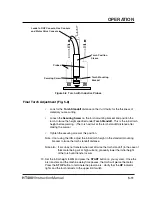
10. Set the
S2
toggle switch to Test Preflow.
Set the preflow flow rate(s) on the
O
2
and/or N
2
flow meters using the MV2 and MV3 metering valve. Select the test
preflow rates from the
Cut Charts.
11. Set S2 to Test Cut Flow . Set the cut flow rate on the O
2
or N
2
flow meters using
the MV1 metering valve. Select the test cut flow rates from the
Cut Charts.
3-97
Содержание HT4001
Страница 1: ...Plasma Arc Cutting System Instruction Manual 802000 Revision 15 HT4001 EN50199 EN60974 1 ...
Страница 142: ...PARTS LIST 6 6 HT4001 Instruction Manual Figure 6 2 HT4001 Power Supply Inside Front Panel 1a 1b 1c 1d 2 99 2 ...
Страница 148: ...PARTS LIST 6 12 HT4001 Instruction Manual Figure 6 5 HT4001 Power Supply Inside Floor 1 2 3b 3a 3c 3d ...
Страница 152: ...PARTS LIST 6 16 HT4001 Instruction Manual Figure 6 7 HT4001 Power Supply Rear Wall Outside 1 2 6 8 7 4 5 9 3 10 6 95 ...
Страница 239: ...e 2 ...
Страница 240: ...e 3 ...
Страница 241: ...e 4 ...
Страница 242: ...e 5 ...
Страница 244: ...e 7 ...
Страница 245: ...e 8 ...
Страница 246: ...e 9 ...
Страница 247: ...e 10 ...
Страница 257: ...KY ...
Страница 258: ...KY ...
Страница 259: ...KY ...
Страница 260: ...KY ...
Страница 261: ...KY ...
Страница 262: ...KY ...
Страница 263: ...KY ...
Страница 264: ...KY ...
Страница 268: ...KY ...
Страница 269: ...KY ...
Страница 270: ...KY ...

