Hydromatic SPX50 Скачать руководство пользователя страница 6

6

around the entire diameter.
Note, these parts should be
discarded and a new seal
assembly installed.

5. If the oil in the seal

chamber was drained, examine
the contents to determine if the
upper seal has been damaged.
Signs of grit or other abrasive
material may indicate that the
upper seal has also been
damaged.  Pressurizing the
motor housing assembly
between 7 and 10 psi and
observing any drop in
pressure will indicate if 
the upper seal is functioning
properly.

NOTE: Upper seal repairs must
be done at a Hydromatic
authorized service center or at
the Hydromatic factory.  Any
unauthorized field repair voids
warranty and the explosion-
proof approval on the CSA
listed pumps.

Reassembly:

1. Remove the ceramic 

portion of the new seal from
the package.  Brush new
dielectric oil around the rubber
portion of the stationary
assembly and into the pocket
in the seal housing.  Note,
keep the oil off the seal face.
Without scratching the seal
face, press the ceramic
stationary portion into the seal
housing.  A piece of PVC pipe
that fits onto the face of 
the seal works well for 
installation.  With clean cloth,
lightly wipe the face of the
seal surface to make sure it is
dirt free.  Remove the rotating
portion of the seal from the
package and lubricate the

inside diameter of the rubber
bellows and the outside
diameter of the shaft.  Place
the seal over the shaft.  Evenly
press on the body of the
rotational assembly and slide it
down the shaft until the seal
faces meet.  PVC pipe with the
inside diameter slightly larger
than the shaft diameter can
work well to press the
rotational assembly into
position.  Once the seal
assembly is in position, place
the spring over the register 
on the rotational portion 
of the seal.

2. Thread the impeller onto the

shaft, making sure that the seal
spring is registered properly
onto the back side of the
impeller.  Place the proper
Loctite fluid on the impeller
retaining nut. Tighten nut 
on shaft.

3. Fill the seal chamber with new

dielectric oil.  An air gap of
10–15% volume must be 
left for the expansion of the
oil when it is at operating
temperature.

4. The motor and impeller

assembly can be installed into
the volute, making sure that
the units are aligned properly.
Install the volute retaining
bolts and tighten.

5. Air tends to trap in the pump

case when water rises in the
sump or when the pump is
lowered into the water after
service.  To vent off this air, a
small hole is drilled into the
volute casting.  Be sure this
vent hole is clean after any
service work on pump. Air
venting is not a problem after
initial start.

Содержание SPX50

Страница 1: ...ion Proof Pumps SPX50 SPX50H NOTE To the installer Please make sure you provide this manual to the owner of the pumping equipment or to the responsible party who maintains the system Pump Installation and Service Manual ...

Страница 2: ...e power source before handling or servicing 7 Any wiring to be done on pumps should be done by a qualified electrician 8 Never operate a pump with a power cord that has frayed or brittle insulation 9 Never let cords or plugs lie in water 10 Never handle connected power cords with wet hands Pumps 11 Pump builds up heat and pressure during operation allow time for pump to cool before handling or ser...

Страница 3: ...rd cord grip and internally through the use of a dielectric potting resin surrounding the electrical wires Internal connection wiring diagrams are shown in page 6 All of the pump fasteners and shafts are made from corrosion resistant stainless steel while the pump castings are made of ASTM A 48 Class 30 cast iron and the multivane vortex impellers are made from Class 20 cast iron General Installat...

Страница 4: ...n explosion proof pump the reading should be above 30 000 ohms If the measured values are below those indicated above the pump may have a lower seal failure and require service On the Hydromatic explosion proof control panels the seal leak test switch tests the seal leak circuit continuity When pushed the seal leak test bulb should light If the test bulb does not light it means either the wiring c...

Страница 5: ...ns All electrical wiring must be in accordance with local code and only qualified electrician should make the installations Complete wiring diagrams are included for use in making the installation All wires should be checked for shorts to ground with an ohmmeter or Megger after the connections are made This is important as one grounded wire can cause failure of the pump control panel or personal i...

Страница 6: ...e Remove the rotating portion of the seal from the package and lubricate the inside diameter of the rubber bellows and the outside diameter of the shaft Place the seal over the shaft Evenly press on the body of the rotational assembly and slide it down the shaft until the seal faces meet PVC pipe with the inside diameter slightly larger than the shaft diameter can work well to press the rotational...

Страница 7: ... may be damaged by lightning 3 Resistance reading of the motor with lead wires disconnected from the control box can determine if trouble is in motor or control box CONDITION Pump is noisy and pump rate is low PROBABLE CAUSE 1 Impeller may be partially clogged with some foreign objects causing noise and overload on the motor CONDITION Grease and solids have accumulated around pump and will not pum...

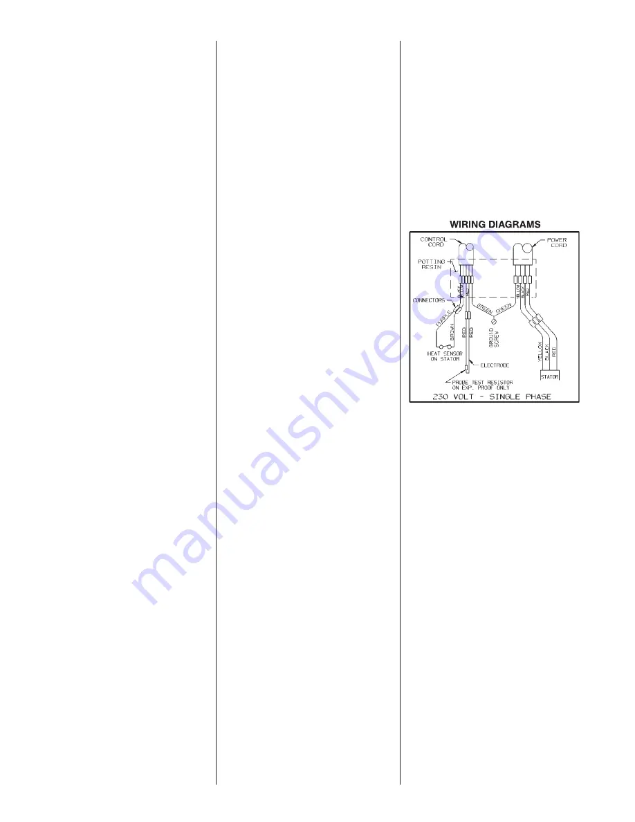
Страница 8: ...8 Pump Wiring Diagrams ...

Страница 9: ...9 Pump Wiring Schematic WIRING SCHEMATIC FOR 230V 1Ø SIMPLEX SYSTEM ...

Страница 10: ...10 Performance Curves ...

Страница 11: ...51 5 13 32 137 2 NPT 9 1 32 229 3 19 32 91 3 31 32 101 239 9 13 32 4 102 4 102 9 5 16 236 241 9 15 32 NPT 1 1 2 4 13 16 122 1 31 32 50 20 508 SPX50 Dimensions in mm SPX50H Dimensions in mm SPX50 SPX50H Dimensional Data ...

Страница 12: ...ing Motor 21571D100 12 Stator Only 21656C103 13 Oil Transformer 1 gal can 1 06 gal 14 Washer Spring 19331A005 2 15 Bearing Ball upper 08565A013 1 16 Ring Retaining 11816A006 1 17 Rotor w Shaft 26859C101 1 18 Bearing Ball lower 0856A018 1 19 Housing Upper Seal 21574D100 1 20 Seal Shaft 21576A010 2 21 Ring Retaining 12588A006 1 22 Electrode w Resistor 22578A003 1 23 O Ring 6 1 8 x 5 7 8 x 1 8 05876A...

Страница 13: ...ing Motor 21571D100 Stator Only 21656C103 13 Oil Transformer 1 gal can 1 06 gal 14 Washer Spring 19331A005 2 15 Bearing Ball upper 08565A013 1 16 Ring Retaining 11816A006 1 17 Rotor w Shaft 26859C101 1 18 Bearing Ball lower 08565A018 1 19 Housing Upper Seal 21574D100 1 20 Seal Shaft 21576A010 2 21 Ring Retaining 12588A006 1 22 Electrode w Resistor 22578A003 1 23 O Ring 6 1 8 x 5 7 8 x 1 8 05876A12...

Страница 14: ..._____________ ______________________________________________ ______________________________________________ ______________________________________________ ______________________________________________ ______________________________________________ ______________________________________________ ______________________________________________ ______________________________________________ __________...

Страница 15: ..._____________ ______________________________________________ ______________________________________________ ______________________________________________ ______________________________________________ ______________________________________________ ______________________________________________ ______________________________________________ ______________________________________________ __________...

Страница 16: ... and shipping charges associated with this warranty and must request warranty service through the installing dealer as soon as a problem is discovered No request for service will be accepted if received after the Warranty Period has expired This warranty is not transferable EXCEPTIONS Hydromatic Special Application Pumps Battery Back Up Sump Pumps Filtered Effluent Pumps Grinder Pumps and 2 1 2 Se...

Отзывы: