Huvitz HOCT-1F/1 Скачать руководство пользователя страница 12


12 


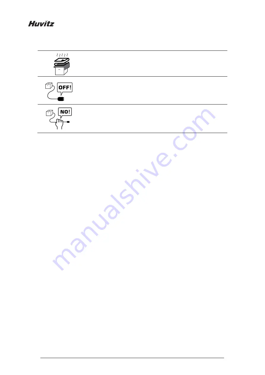
Be careful not to block the fan of the instrument. 


Don’t  plug  the  AC  power  cable  into  the  outlet  unless  all  parts  of  the 

instrument  are  completely  connected.  Otherwise,  it  will  cause  severe 

damage on the instrument. 


Pull out the power cable with holding the plug, not the cord. 

To avoid risk of electric shock, this equipment must only be connected to a 

supply mains with protective earth. 


For  the  normal  operation  of  the  instrument,  please  keep  the  ambient  temperature  is  10

  ~  35

humidity  is  30%  ~  90%  and  atmospheric  pressure  is  800  ~  1060hpa.  For  the  Transportation  of  the 
instrument,  please  keep  the  ambient  temperature  is  -40

  ~  70

,  humidity  is  10%  ~  95%  and 

atmospheric pressure is 500 ~ 1060hpa. For the Storage of the  instrument, please keep the ambient 
temperature  is  -10

  ~  55

,  humidity  is  10%  ~  95%  and  atmospheric  pressure  is  700  ~  1060hpa. 

Avoid environments where the equipment is exposed to excessive shocks or vibrations. 


Содержание HOCT-1F/1

Страница 1: ...OPTICAL COHERENCE TOMOGRAPHY HOCT 1F 1 USER MANUAL ...

Страница 2: ... or omissions or for any consequences resulting from the use of the information contained herein HUVITZ reserves the right to make changes in its products or product specifications at any time and without prior notice and is not required to update this documentation to reflect such changes Revision History Revision Date Approval Description A appDate1 app1 First issued 9000ENG0040 A 2018 01 10 201...

Страница 3: ... HOCT 1F only 24 5 Installation Procedure 25 5 1 System installation 25 6 Operation 28 6 1 Software 28 6 2 SETUP Mode 30 6 3 General Operation 33 6 4 Anterior segment image operation optional 45 6 4 1 Preparation for anterior segment operation 45 6 4 2 Capturing anterior segment 46 6 5 Analyze 51 6 5 1 Entering Analysis screen 51 6 5 2 OCT Macular 3D Analysis screen 52 6 5 3 OCT Disc 3D Analysis s...

Страница 4: ...4 9 EMC INFORMATION 103 10 SERVICE INFORMATION 105 11 SOFTWARE LICENSE AGREEMENTS 106 ...

Страница 5: ...opriately within the text of this manual to highlight safety related information or information requiring special emphasis All users operators and maintainers must be familiar with and pay particular attention to all signs of Warnings and Cautions Warning indicates the presence of a hazard that could result in severe personal injury death or substantial property damage if ignored Caution indicates...

Страница 6: ... This symbol identifies a safety note Ensure you understand the function of this control before using it Control function is described in the appropriate User s or Service Manual Identifies the point where the system safety ground is fastened to the chassis Protective earth connected to conductive parts of Class I equipment for safety purposes Indicates the Manufacturer Indicates the date of manuf...

Страница 7: ...7 HOCT 1F 1 Class I Laser Product CE for RoHS RoHS Directive Compliance 2011 65 EU WEEE indicating separate collection for electrical and electronic equipment ...

Страница 8: ...f equipment in rated voltage less than 125Vac minimum 6A Type SJT or SVT 18 3AWG 10A max 3 0m long One end with Hospital Grade Type NEMA 5 15P Other end with appliance coupler For use of equipment in rated voltage less than 250Vac minimum 6A Type SJT or SVT 18 3AWG 10A max 3 0m long One end terminated with blade attachment plug HAR Type NEMA 6 15P Use instrument that comply with IEC60601 1 in the ...

Страница 9: ... distance is just 15mm that the front lens is very close to patient s eye This instrument includes lithium battery This hazardous material needs to be disposed of properly to limit environmental pollution Please contact to the professional waste disposal company Do not install any software on OCT built in computer without our consent The manufacturer is not responsible for any failure due to rando...

Страница 10: ...1 x 107 sec for Kerato ring Auto Manual Tracking 9 5 x 10⁷ sec for Kerato focus Auto Manual Tracking 1 0 x 108 sec for Split focus Optimizing 9 1 x 10⁵ sec for external fixation lamp 4 8 x 10⁷ sec for SLD Laser OCT scanning 1 936 114 pulses for the light source of fundus image capture Note 1 The exposure time and number of pulses from all light sources is cumulative and additive Note 2 If the inte...

Страница 11: ...e are big changes in temperature Optimal temperature range for normal operation is from 10 C to 35 C Humidity 30 90 Where there is hot equipment nearby Where the humidity is extremely high or there is a ventilation problem Where the instrument is exposed to excessive shocks or vibrations Where the instrument is exposed to chemical material or explosive gas Be cautious so that things like dust and ...

Страница 12: ... a supply mains with protective earth For the normal operation of the instrument please keep the ambient temperature is 10 35 humidity is 30 90 and atmospheric pressure is 800 1060hpa For the Transportation of the instrument please keep the ambient temperature is 40 70 humidity is 10 95 and atmospheric pressure is 500 1060hpa For the Storage of the instrument please keep the ambient temperature is...

Страница 13: ...perated by a trained and qualified person or under his or her supervision 7 Repair of this instrument must be conducted by HUVITZ s service technicians or other authorized persons 8 Maintenance by users must observe the User s Manual and Service Manual Any additional maintenance may only be performed by HUVITZ s service technicians or other authorized persons 9 Manufacturers are responsible for th...

Страница 14: ...ontact customer service center 20 To avoid the risk of electric shock this instrument must only be connected to protective earth 21 Do not place the instrument where it is difficult to operate the disconnecting device disconnecting device power cable 22 The equipment may be impaired if it is used in a manner not specified by the manufacturers or manual 23 External equipment intended for connection...

Страница 15: ...cular degeneration and so on which are occurred at a macular an optic disk an inner structure of retina and a cornea 3 3 Classification Classification of product Class II according to Annex IX Rule 10 of the Medical Device Directive 93 42 EEC as amended by 2007 47 EC Resistance against electric shock Class I earthed Protection class against electric Type B Head rest chinrest paper Classification o...

Страница 16: ...obtained interference light is dispersed into individual wavelengths and detected by the line image sensor The detected light is converted to signals and then computed to form images With the anterior segment adapter optional a fundus tomogram can be formed 3 7 Applied Standard List IEC EN 60601 1 MEDICAL ELECTRICAL EQUIPMENT Part 1 General requirements for safety IEC EN 60601 1 2 Medical electric...

Страница 17: ...capturing image 4 User Lock Lock for fixing body to base frame 5 OPT button Button for optimizing OCT signal 6 1 6 2 Align index mark Mark for indicating center of body and base 7 Base Power button Button for turning power of internal PC on off When the power is on white light is lit 9 1 Power switch Switch for power on off 9 2 Power inlet Inlet for connecting power cable 10 Headrest Eye level mar...

Страница 18: ...18 Rear View ...

Страница 19: ...distance 5 Headrest Objective lens cap Cap for protecting objective lens 8 Base External port Port for communicating internal or external device 8 1 RS 232 port Port for communicating internal PC board and main board 8 2 RGB port Port for external display device 8 3 DP port Port for communicating external DP device 8 4 LAN port Port for external network 2 ports 8 5 USB port Port for internal or ex...

Страница 20: ...left eye 4 AUTO S Show auto shooting selection status 5 AUTO T Show auto tracking selection status 6 FIXATION Select position of internal fixation target 7 C LENS Show compensation lens status 0 No compensation lens is used Minus compensation lens is used Plus compensation lens is used 8 IR ILL Select brightness level of IR light for fundus observation Normal Bright mode is toggled by clicking 9 S...

Страница 21: ...Reset scan position to center 14 Focus Move in accordance with focus of patient s eye 15 Ref M Move reference mirror position for OCT scan 16 Flash Change brightness level of white light for capturing fundus image 17 Scan Start Start OCT scan 18 Scan direction Horizon vertical changes are possible ...

Страница 22: ...on of current OCT scan image displayed on the right 4 Move scan position Change previous next OCT scan image 5 Play image Display captured OCT scan image continuously 6 SSI SSI Scan Signal Index Show quality index of scan image 7 Scan information Display setting information of scan image 8 Fundus image Show captured fundus image 9 OCT image Show captured OCT image 10 Analyze Save the camera DATA a...

Страница 23: ... Observation screen Refer 4 2 1 OCT Fundus mode Observation screen for uncommented item No Name Function 1 Signal Level Mode can be changed Confirmation screen Refer 4 2 1 OCT Fundus mode Confirmation screen for uncommented item ...

Страница 24: ...e mode Single Capture one fundus image Panorama Capture maximum 7 images and stitch it 2 IR En Change brightness of IR fundus image 3 Optimize Find focus position automatically by split focus image Confirmation screen Refer 4 2 1 OCT Fundus mode Confirmation screen for uncommented item No Name Function 1 Fundus information Display setting information of fundus image ...

Страница 25: ...t on a stable table Loosen the two packing lock screw under the main body Unscrew the user lock lever on the body Attach two base packing lock cap while moving body left and right with joystick Attach the chinrest paper to the chinrest 5 Packing lock User lock Joystick Packing lock cap ...

Страница 26: ... screw driver Connect communication cable of external device Close COVER BASE VENT with screw driver Check the power switch on the bottom right of base is off O position Connect power cable to power inlet Also connect the other side of power cable to electric outlet External LED Headrest COVER BASE VENT Power switch Power inlet ...

Страница 27: ...pressing power switch I position Turn on the internal PC by pressing power button Check there is no error during initialize process Wait for until the initialization is complete Check the movement of body with joystick Also check the movement of motorized chinrest with chinrest button Objective lens cap Power switch Power button Chinrest button Chinrest Joystick ...

Страница 28: ...ion 6 1 Software Input user ID and password for login Press resist patient icon and input patient information If patient is resisted already skip this step Select patient and check patient information is correct 6 ...

Страница 29: ...29 HOCT 1F 1 When you select a patient the screen changes Enter observation mode by pressing measure icon The screen of observation mode is as follow ...

Страница 30: ... screen To press CANCEL button will discard the changes and exit the setup screen 1 System Settings Device Name Set Device Name Server IP Web Viewer Server IP address setting Sever Port Web Viewer Server port setting Sleep Time Sleep mode setting Update Period Web Viewer patient information update period setting Auto Data Trans Set the function to transfer the measured data to Web Viewer automatic...

Страница 31: ...utomatically generated patient ID PID Number Length The function to set the length of automatically generated patient id Date Format Format of the date Year Month Day 3 Measure Settings Startup Measure Set the initial mode of measurement Auto Tracking Auto Tracking ON OFF setting Auto Shot Auto Shot ON OFF setting Auto Scan Start Auto Scan Start ON OFF setting Flash Level Adjust the flash level va...

Страница 32: ...5 Analysis Settings Scan Image Color Set the default representation mode of Bscan image to be either gray pseudo color or inversed gray Scan Image Level Adjust the gray level values of Bscan image Auto Chart Center To move the center of the ETDRS or RNFL chart to the detected center of the macular or the disc Fundus Auto Enhance Apply the standard values of brightness contrast UB and VR to the mea...

Страница 33: ... clean cotton swab or gauze Remove a single sheet of chinrest paper if the chinrest paper is used 2 Align left right index mark B and front index mark A of body and base with joystick 3 Let the patient sit in front of instrument 4 Set the mode and environment as following ...

Страница 34: ...age 4 2 Set capture region with the capture region combo box OCT Fundus Macular Disc Anterior OCT Fundus Single Panorama 4 3 In OCT or OCT Fundus mode set scan type and options for the selected scan region Scan region Scan type Available option Scan along a line for macular Scan along horizontal lines and vertical lines for macular Scan along 12 radial lines centered at macular ...

Страница 35: ... along 24 lines in the square area centered at macular Scan a rectangular area closely Scan along 12 radial lines centered at disc Scan along 24 lines in the square area centered at disc Scan a rectangular area closely ...

Страница 36: ...Bscan Lines Choose the number of B scans that constitute one measurement Possible options depend on the number of A scans set Overlap Choose the number of B scans to be averaged to produce one B scan image Possible options are enumerated Direction Set a direction which is horizontal or vertical Space Set an interval between neighboring scan lines Enface Set on or off for a live enface image Sensit...

Страница 37: ... different number of overlapping images Overlap 1 Overlap 15 Overlap 30 Overlap 45 Scan Range Select the size of area to be measured Bscan images of each Scan Ranges Macular Line Analysis Screen Macular 3D Analysis Screen Scan Range 6 Scan Range 6x6 Scan Range 9 Scan Range 9x9 Scan Range 12 Scan Range 12x9 ...

Страница 38: ... shooting is not supported for anterior capture mode 4 5 Set auto tracking mode Auto tracking is on Auto tracking is off If auto tracking is on patient s eye is automatically tracked to center and focused when patient s eye is inside tracking region Auto tracking is not supported for anterior capture mode 4 6 Set compensation lens mode on if the eyesight of patient is out of 13 to 13 diopter Once ...

Страница 39: ...Let the patient s chin put on the chinrest 5 2 Let the patient s forehead adhere to headrest 5 3 Move up or down chinrest with the chinrest button B on the body to fit the level of patient s eye to the eye level mark A on the headrest 6 Instruct patient to watch internal fixation LED to fix patient eyes Also instruct patient to open eye widely not to blink 7 Move body with joystick until patient s...

Страница 40: ...ndicator bar disappears 8 2 If the pupil of patient is smaller than 16 blue align dot press S pupil icon to capture in small pupil mode 8 3 Move joystick little by little until orange target mark A appears 8 4 If auto tracking is on alignment and focus is automatically accomplished in tracking region 8 5 If orange arrow A appears during auto tracking it means auto tracking module go to the limit o...

Страница 41: ...rror using slide bar 9 4 Press the button on joystick to capture image If auto shooting is on 9 2 Optimize and 9 4 Capture is accomplished automatically 9 5 Check the result and decide to store or discard and retry Check previous next OCT image by pressing move scan position button Check continuous OCT image continuously by pressing play image button Check SSI for image quality SSI Scan Signal Ind...

Страница 42: ... position of internal fixation target is also changed D Try to change scan position by dragging scan range while scan range icon turned on If reset scan position icon is pressed scan position moves to the default center position 10 Capture image and check image quality in OCT mode 10 1 When alignment and focus is done press scan start icon to start OCT scan If alignment and focus is in good condit...

Страница 43: ...l We recommend capture normal or good status in general But you don t have to retry when image is satisfactory but SSI is low because SSI depends on patient s eye conditions If the image is satisfactory press OK icon to save image If the image is not satisfactory press retry icon and retry image capturing A Try moving internal fixation target position by pressing fixation icon and changing positio...

Страница 44: ...card and retry If the image is satisfactory press OK icon to save image If the image is not satisfactory press retry icon and retry image capturing A If fundus image result too bright or too dark because of lighting regulate the flash intensity using flash icon in observation mode B If fundus image is too dark because of small pupil size of patient try small pupil mode by using small pupil icon in...

Страница 45: ...n 2 Thread anterior segment adapter A to objective lens holder B and check there is no tilting or misalignment of adopter Don t lock it too hard 3 Check anterior headrest rubber is clean 4 Hang anterior headrest rubber to headrest of instrument C first then press anterior headrest rubber to be fixed firmly 5 Check the mounted anterior headrest rubber does not incline ...

Страница 46: ...nce is just 15mm that the front lens is very close to patient s eye 3 Capture image and check image quality in anterior radial or anterior 3D mode 3 1 Alignment and focus Move body with joystick slowly to align anterior scan line A and center of patient s eye B Start OCT scan by pressing scan start icon Move body with joystick slowly until section of cornea appears on the screen 3 2 Measuring curv...

Страница 47: ...e button if needed Check SSI for image quality if needed SSI Scan Signal Index indicates level of image quality SSI means signal to background ratio and displayed on a scale of 10 with a bar graph SSI larger than 8 means Good 5 8 means Normal less than 5 means Poor in general We recommend capture normal or good status in general But you don t have to retry when image is satisfactory but SSI is low...

Страница 48: ...can range while scan range icon turned on If reset scan position icon is pressed scan position moves to the default center position 4 Capture anterior chamber angle image and check image quality in ACA line mode 4 1 Alignment and focus Guide patient to gaze left hand side or right hand side according to the interested part Move body with joystick slowly to align anterior scan line A and objective ...

Страница 49: ... a bar graph SSI larger than 8 means Good 5 8 means Normal less than 5 means Poor in general We recommend capture normal or good status in general But you don t have to retry when image is satisfactory but SSI is low because SSI depends on patient s eye conditions Check image quality This function available on OCT Fundus mode If the image is satisfactory press OK icon to save image If the image is...

Страница 50: ...green cross position changes the position of internal fixation target is also changed D Try to change scan position by dragging scan range while scan range icon turned on If reset scan position icon is pressed scan position moves to the default center position 5 Repeat procedure for the other eye if needed 6 When capturing anterior segment is done remove anterior segment adapter and anterior headr...

Страница 51: ...ately after scanning To enter analyze mode from measurement confirm screen press the analyze icon from the captured image screen 2 Analysis from measurement list Select a measurement to analyze by clicking and press the analyze button or simply double click on a measurement ...

Страница 52: ...ort screen of the current measurement 6 EXPORT Capture current screen and store it 7 LEVEL ADJUST Adjust contrast of Bscan 8 THICKNESS Select the analysis range between ILM GCL ILM RPE 9 SETUP Moves to User setting screen 10 IR Fundus Select between IR Fundus Color Fundus if color fundus result is available 11 Scan range The range on retina the current OCT measurement scanned 12 Scan position Indi...

Страница 53: ...scan image to a Full screen 20 Move scan position Move to the previous or the next Bscan image 21 Bscan 2 Another Bscan screen to display position different from Bscan 1 1 2 Select analyze mode choosing OD OU OS icon OD Right eye Analysis OU Both eyes Analysis OS Left eye Analysis When selecting OU among OD OU OS screen changes to OU analysis screen shown below ...

Страница 54: ...con shows REPORT screen shown below No Name Function 1 Previous screen Go back to analysis screen 2 PRINT Save the current report showing as PDF file or print to a connected printer 3 Report Preview Preview of generated report ...

Страница 55: ...55 HOCT 1F 1 1 5 2 Selecting PRINT icon shows printer option window 1 5 3 Select REPORT icon at OU screen to change to REPORT screen ...

Страница 56: ...n shows a pop up window shown below and the current screen shot is captured and stored in user selected folder 1 7 Selecting LEVEL ADJUST icon shows an adjustable pop up window shown below Use Slide Bar to control Bscan Contrast ...

Страница 57: ...nalysis criteria to ILM GCL ILM RPE Set Analysis criteria to ILM RPE Analysis results will be displayed according to each setting value 1 10 Fundus image can be chosen from monochromatic IR fundus image or color fundus image No Name Function 1 Red Free Shows Red Free image from Color Fundus ...

Страница 58: ...rlay Control icon to make the analysis result overlayed on Macular image Icon ON OFF ON screen Function Displays Scan Domain Displays Scan Direction Displays enface image Displays thickness map image Displays ETDRS Chart ...

Страница 59: ...e Screen Function Displays thickness map in pseudo color Displays thickness based on the previously set Thickness Layer ILM RPE ILM GCL Displays ETDRS Chart Displays following measured values Average Thickness Fovea Thickness Center Thickness Superior Thickness Inferior Thickness ...

Страница 60: ...th measured using measurement icon OFF Hides the measurements Selecting two points with the length measurement icon ON on Bscan screen shows the length between the two points Latest data can be deleted by selecting Undo Icon Only usable with measurement result Icon ON Click Segmentation icon to show Bscan Layer ALL ILM GCL RPE are selective ...

Страница 61: ...ing Color Icon displays Bscan image in pseudo color Selecting Gray Icon displays Bscan image in grayscale Selecting Invert Icon displays Bscan image in inverted grayscale Selecting HD Icon indicates HD quality Bscan image ...

Страница 62: ...62 1 19 Selecting FULL Screen Icon shows the current Bscan image in full screen ...

Страница 63: ...to report screen of the current measurement 6 EXPORT Capture current screen and store it 7 LEVEL ADJUST Adjust contrast of Bscan 8 THICKNESS Select the analysis range between ILM RNFL ILM RPE 9 SETUP Moves to User setting screen 10 IR Fundus Select between IR Fundus Color Fundus if color fundus result is available 11 Scan range The range on retina the current OCT measurement scanned 12 Scan positi...

Страница 64: ...n image to a Full screen 20 Move scan position Move to the previous or the next Bscan image 21 Bscan 2 Another Bscan screen to display position different from Bscan 1 1 2 Select analyze mode choosing OD OU OS icon OD Right eye Analysis OU Both eyes Analysis OS Left eye Analysis When selecting OU among OD OU OS screen changes to OU analysis screen shown below ...

Страница 65: ...ORT icon shows REPORT screen shown below No Name Function 1 Previous screen Go back to analysis screen 2 PRINT Save the current report showing as PDF file or print to a connected printer 3 Report Preview Preview of generated report ...

Страница 66: ...66 1 5 2 Selecting PRINT icon shows printer option window 1 5 3 Select REPORT icon at OU screen to change to REPORT screen ...

Страница 67: ...T icon shows a pop up window shown below and the current screen shot is captured and stored in user selected folder 1 7 Selecting LEVEL ADJUST icon shows an adjustable pop up window shown below Use Slide Bar to control Bscan Contrast ...

Страница 68: ...is criteria to ILM RNFL ILM RPE Set Analysis criteria to ILM RPE Analysis results will be displayed according to each setting value 1 10 Fundus image can be chosen from monochromatic IR fundus image or color fundus image No Name Function 1 Red Free Shows Red Free image from Color Fundus ...

Страница 69: ...ct Overlay Control icon to make the analysis result overlayed on Disc image Icon ON OFF ON screen Function Displays Scan Domain Displays Scan Direction Displays enface image Displays thickness map image Displays TSNIT Range ...

Страница 70: ...o show the analysis result Analyze Screen Function Displays thickness map in pseudo color Displays TSNIT Graph Displays RNFL Chart Displays following measured values C D Ratio Horz C D Ratio Vert Cup Area Disc Area Cup Volume Disc Volume ...

Страница 71: ...length measured using measurement icon OFF Hides the measurements Selecting two points with the length measurement icon ON on Bscan screen shows the length between the two points Latest data can be deleted by selecting Undo Icon Only usable with measurement result Icon ON Click Segmentation icon to show Bscan Layer ALL ILM RNFL RPE are selective ...

Страница 72: ...olor Icon displays Bscan image in pseudo color Selecting Gray Icon displays Bscan image in grayscale Selecting Invert Icon displays Bscan image in inverted grayscale Selecting HD Icon indicates HD quality Bscan image ...

Страница 73: ...73 HOCT 1F 1 1 19 Selecting FULL Screen Icon shows the current Bscan image in full screen ...

Страница 74: ...ft eye OU both eyes 3 Date Displays the date the measurement was taken 4 MEASURE Moves to capture screen after finishing Analysis 5 REPORT Moves to report screen of the current measurement 6 EXPORT Capture current screen and store it 7 LEVEL ADJUST Adjust contrast of Bscan 8 THICKNESS Select the analysis range between Epi Bowman s Epi Endo 9 SETUP Moves to User setting screen 10 Scan position Indi...

Страница 75: ... HOCT 1F 1 1 2 Select analyze mode choosing OD OU OS icon OD Right eye Analysis OU Both eyes Analysis OS Left eye Analysis When selecting OU among OD OU OS screen changes to OU analysis screen shown below ...

Страница 76: ...con show REPORT screen shown below No Name Function 1 Previous screen Go back to analysis screen 2 PRINT Save the current report showing as PDF file or print to a connected printer 3 Report Preview Preview of generated report ...

Страница 77: ...77 HOCT 1F 1 1 5 2 Selecting PRINT icon shows printer option window 1 5 3 Select REPORT icon at OU screen to change to REPORT screen ...

Страница 78: ...n shows a pop up window shown below and the current screen shot is captured and stored in user selected folder 1 7 Selecting LEVEL ADJUST icon shows an adjustable pop up window shown below Use Slide Bar to control Bscan Contrast ...

Страница 79: ...sis Criteria to EPI Endo Analysis results will be displayed according to each setting value 1 12 Select Bscan analysis tool on Bscan image to analyze the Bscan currently displayed Icon ON OFF Screen and Function ON Shows the length and the angle measured using length measurement icon and angle measurement Icon OFF Hides the measurements ...

Страница 80: ...leted by selecting Undo Icon Only usable with measurement result Icon ON Selecting three points with the angle measurement Icon ON shows the angle made by the three points Latest data can be deleted by selecting Undo Icon Only usable with measurement result Icon ON Selecting Color Icon displays Bscan image in pseudo color ...

Страница 81: ...HOCT 1F 1 Selecting Gray Icon displays Bscan image in grayscale Selecting Invert Icon displays Bscan image in inverted grayscale 1 13 Selecting FULL Screen Icon shows the current Bscan image in full screen ...

Страница 82: ... screen of the current measurement 6 EXPORT Capture current screen and store it 7 SETUP Changes to User setting screen 8 Navigation Indicates the position of fundus image displayed in main screen 11 when it s magnified 9 Red Free Analyze Fundus Image using Red Free 10 RGB Channel Selection of RGB Channel 11 Fundus Image Shows captured Fundus Image 12 Direction Indication Mark Indicates the orienta...

Страница 83: ... HOCT 1F 1 1 2 Select analyze mode choosing OD OU OS icon OD Right eye Analysis OU Both eyes Analysis OS Left eye Analysis When selecting OU among OD OU OS screen changes to OU analysis screen shown below ...

Страница 84: ...con shows REPORT screen shown below No Name Function 1 Previous screen Go back to analysis screen 2 PRINT Save the current report showing as PDF file or print to a connected printer 3 Report Preview Preview of generated report ...

Страница 85: ...85 HOCT 1F 1 1 5 2 Selecting PRINT icon shows printer option window 1 5 3 Select REPORT icon at OU screen to change to REPORT screen ...

Страница 86: ...6 Selecting EXPORT icon shows a pop up window shown below and the current screen shot is captured and stored in user selected folder 1 9 Use Red Free ON OFF icon to analyze Fundus Image with Red free Screen ...

Страница 87: ...played in monochromatic image RGB Channel R Channel G Channel B Channel 1 13 Images can be adjusted using Slide Bar of Adjustment Control Adjustment of Brightness Adjustment of Contrast Adjustment of UB Adjustment of VR Resetting of individual Adjustment Resetting of all Adjustment ...

Страница 88: ...results measured by length measurement Icon area measurement Icon C D ration measurement Icon on Fundus Image OFF Hides the measurements Selecting two points with the length measurement icon shows the length between the two points Latest data can be deleted using Undo Icon Only usable with measurement result Icon ON ...

Страница 89: ...sult Icon ON With C D ratio measurement switch on clicking a point on the fundus image produces two concentric circles at the point C D ratio is calculated as the ratio of area of the two circles The shape and size of each circles are adjusted by dragging the marks on the circles Latest data can be deleted using Undo Icon Only usable with measurement result Icon ON ...

Страница 90: ...Function Back to original size 100 using Fit Icon Magnify Fundus Image using Zoom In Icon Magnified image can be dragged and be moved to any position Maximum magnification ratio is 200 Reduce the magnified image using zoom out icon Image will not be reduced to smaller than the original size ...

Страница 91: ...n 1 Exit HOCT software and Power off Select the Patient information icon in the upper left corner of the screen Select the Previous screen icon in the upper left corner of the screen Select the Power Off icon from the bottom left corner of the screen ...

Страница 92: ...nd the body of HOCT to the lowest position before Power off This is for packaging Be sure to select the Packing Mode in order to place the equipment in the packing box 2 Turn off external devices monitor etc if any external device is connected 3 Turn the power switch off O on the base plate Power switch NOTE ...

Страница 93: ...oft cloth For severe stains wipe with a soft cloth with neutral detergent diluted with water Do not use organic solutions such as thinner or benzene Wipe the touch screen with dry soft cloth Do not use sponge or cloth soaked with large amount of liquid Do not press hard or place magnetic objects near the touch screen 3 Part of patient contact Wipe the headrest and the chinrest with a clean cotton ...

Страница 94: ...inrest 2 Replacing fuse Ensure the power switch of device off O Remove power cable from inlet Pull out fuse holder in the inlet with a tweezers Replace two new fuses in the fuse holder Be sure to check the fuse specification for the replacement 250V T 3 15AL Insert fuse holder into the inlet 6 6 4 Calibration Note Huvitz recommends to calibrate the system once a year Contact to the HUVITZ s servic...

Страница 95: ...Remove chinrest paper Mount Model eye as shown below and then fix it using two paper pins Align the center of the Model eye with the objective lens using joystick and chinrest button 2 Checking working distance Select FUNDUS measurement in MEASURE mode Chinrest button Joystick ...

Страница 96: ... the target mark circular orange to be displayed KERATO SETUP shall be performed when the Working dot is extremely distorted while the target mark circular orange displayed 3 Checking anterior lightning LED Select FUNDUS measurement in MEASURE MODE Check anterior lighting LED They consist of six dots except two center dots out of eight dots at anterior screen KERATO SETUP shall be performed after ...

Страница 97: ...e asymmetric areas as right picture from the measured images If there are some re boot the device and measure again Check if there are any blurriness or smear as below picture from the scanned images If blurriness or smear appears clean the finger prints or stain on the objective lens NG OK ...

Страница 98: ...utomatically when the alignment and focusing is correct and let the Bscan IR Fundus and real time Enface screen to be displayed as below picture using Optimize function Check if the Split Focus is aligned as straight line in IR FUNDUS screen Check if the Retina image of the Bscan screen is in between the green guidelines Check if the real time enface video marked with red rectangle shows grid patt...

Страница 99: ...y not be looking at the fixation target at the time of image capture Instruct the patient to focus on the fixation target The intended part may be outside the range for image captures Insert a compensation lens The quality of the captured image is low The objective lens or the lens of Anterior segment adapter may be contaminated Perform the cleaning The patient s eyelid or eyelashes may be interfe...

Страница 100: ...8 1 Standard Accessories Chinrest paper Touch pen Power cable Fuse 250V T 3 15A Dust cover External LED Blower User manual Packing lock cap Model Eye anterior headrest rubber optional Anterior segment adapter optional USB memory optional 8 ...

Страница 101: ...um pupil diameter 4 0 mm Normal mode 3 3 mm Small pupil mode Flash light White light 10 levels Pixel pitch at fundus 4 63 um Common specification Working distance 33 mm Display 12 1 inch 1280x800 pixel Touch panel color LCD Dioptric compensation for patient s eye 33D 33D total 13D 13D with no compensation lens 7D 33D with plus compensation lens 33D 7D with minus compensation lens Internal fixation...

Страница 102: ...102 8 3 Drawings of System ...

Страница 103: ...st IEC 60601 test level Appropriateness level Electrostatic discharge ESD IEC 61000 4 2 contact 8 kV in the air 15 kV contact 8 kV in the air 15 kV Electric rapid transients bust IEC 61000 4 4 power supplying line 2 kV input output line 1 kV power supplying line 2 kV input output line 1 kV Surge IEC 61000 4 5 between lines 1 kV between line and grounding 2 kV differential mode 1 kV common mode 2 k...

Страница 104: ...1F purchaser or user needs to confirm whether HOCT 1 1F is sued at this environment Tolerance test IEC 60601 test conditions Appropriateness level Conductivity RF electromagnetic field IEC 61000 4 6 Radioactivity RF electromagnetic field tolerance IEC 61000 4 3 3 Vrms 150 kHz 80 MHz 10 V m 80 MHz 2 7 GHz scope 3 Vrms 10 V m ...

Страница 105: ... 7 years after stopping to produce the product Parts to be repaired by qualified service manpower 1 5 Parts below are consumable in their characteristics or the quality of them shall degraded after the long time use User should not replace them by him or herself Please contact to Huvitz s agent for the replacement if these parts are consumed enough or degraded by the longtime use 1 6 Back up batte...

Страница 106: ...ading the Software to a temporary memory such as RAM of a computer or installing the Software on a fixed memory such as a hard disk When the Software is used on multiple computers you must obtain the same number of the licenses as the number of computers where the Software will be used even if the Software will not be used concurrently on multiple computers Installing the Software into a fixed mem...

Страница 107: ... INCIDENTAL INDIRECT CONSEQUENTIAL OR SPECIAL DAMAGES OR ANY LOST REVENUES PROFITS DATA OR INFORMATION ARISING OUT OF OR RELATED TO THE USE OF OR INABILITY TO USE SOFTWARE EVEN IF HUVITZ IS NOTIFIED OF THE POSSIBILITY OF SUCH DAMAGES LOSS CLAIMS OR COSTS 7 FORCE MAJEURE In no event HUVITZ will be liable to you for any delay or failure in the performance of its obligations under this Agreement if a...

Страница 108: ...regulations and may be subject to export laws and regulations in other countries You agree to comply strictly with such export laws and regulations 13 SEVERABILITY If any Section in this Agreement is found to be void or unenforceable by applicable law such Section will be deleted automatically and the remaining Sections of this Agreement will remain in full force and effect 14 NO WAIVER The delay ...

Отзывы: