background image

Field Application Department

2018 . 10 . 02 (r1)

28/63

[Execute the calibration for the IOP measurement]

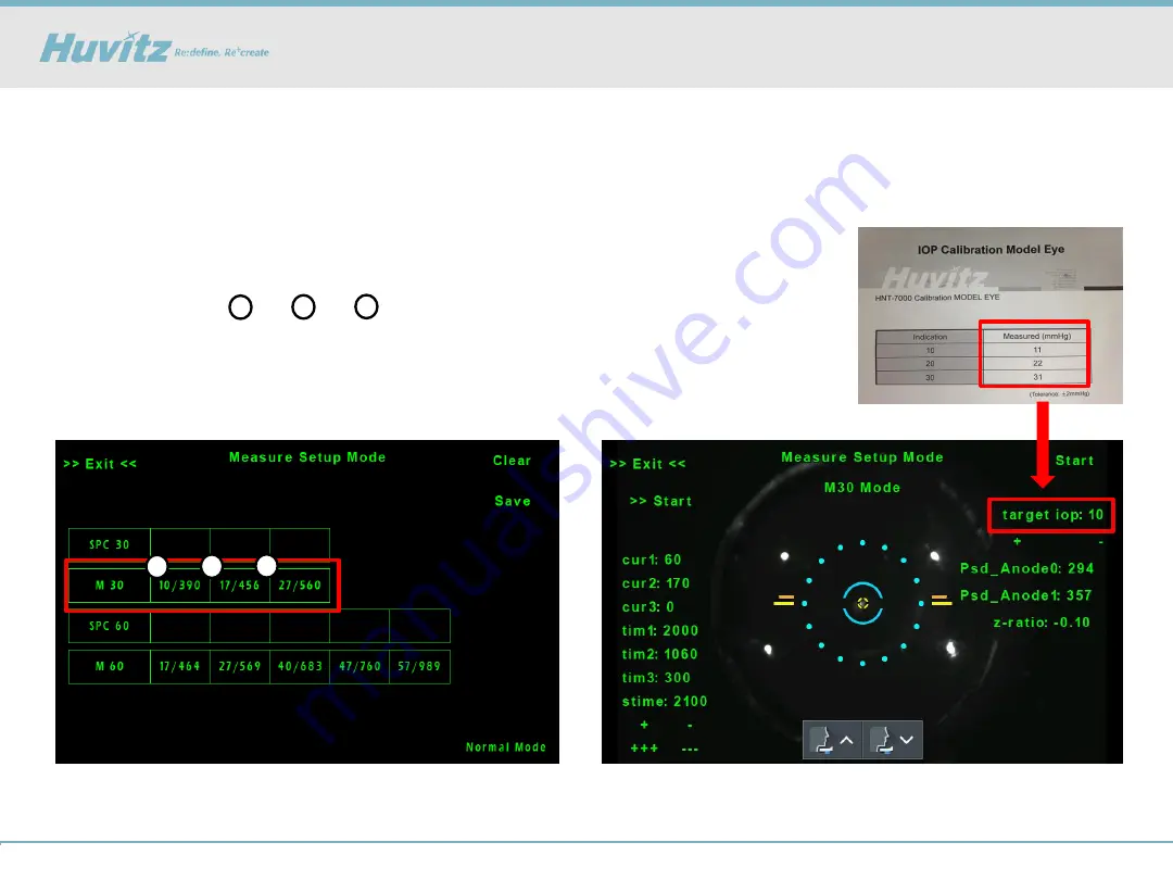
1. Press the table space to start IOP setup

- 10 ~ 30 mmHg Model eye setup

- Set up 

in order

2. Set the target IOP of the current model eye 

- Adjust target IOP with “+”, “-” buttons

1

3

2

4) How to do calibration for IOP

[HNT-1/1P] Data issue_IOP Calibration

1

3

2

Содержание HNT-1

Страница 1: ...Field Application Department 2018 10 02 r1 1 63 HNT 1 1P Troubleshooting ...

Страница 2: ...Field Application Department 2018 10 02 r1 2 63 Contents 1 Auto Tracking issue 2 Data issue 3 Connection with HRK MATE 4 Assembly Disassembly 5 Upgrade the software 6 Engineer Setup Mode ...

Страница 3: ...Field Application Department 2018 10 02 r1 3 63 1 Auto Tracking issue HNT 1 1P Auto Tracking issue ...

Страница 4: ...cification comparisons MANUFACTURER NIDEK HUVITZ PRODUCT NT 530P HNT 1 1P Motor Working Range Y 15mm X 5mm Z 5mm Y 15mm X 5mm Z 5mm 2 Working Range HNT 1 and 1P movement range is same with NIDEK s tonometer Y 15mm X 5mm Z 5mm HNT 1 1P Auto Tracking issue ...

Страница 5: ...d left up and down the indicator is displayed Move the joystick lever toward the patient Move the joystick lever toward the operator Move up by rotating the joystick lever to the clockwise Move down by rotating the joystick lever to the counter clockwise Move the joystick lever to the left Move the joystick lever to the right HNT 1 1P Auto Tracking issue_Focus Indicator ...

Страница 6: ...ation Department 2018 10 02 r1 6 63 We provide the quick guide in the product box to minimize any issues that occur during installation from the 11th of June 2018 Reference HNT 1 1P Auto Tracking issue_Quick guide ...

Страница 7: ...d image 3 Stabilized the movement of chinrest to avoid being stuck at bottom side 4 Added the Z axis guide message Front Rear on screen when focusing on target with 3D Auto Tracking mode 5 Changed movement type of X axis center when shift the measurement type from Tracking mode to manual mode 6 Stabilized the serial communication for transferring data 7 After taking ACA image Enable to take Anteri...

Страница 8: ... 1 1P 4 Select Serial Port Transmit menu 5 Choose HNT 1 1P bin file then press OK button 6 After downloading turn off and on the HNT 1 1P If the version checked is earlier than 1 0 4 proceed to 1 0 4 or later as follows It should takes around 5minutes How to upgrade the software The Screen of progress with upgrade HNT 1 1P Auto Tracking issue_the software 4 Upgrade the Software to the latest versi...

Страница 9: ...ment 2018 10 02 r1 9 63 5 How to adjust the LED brightness Enter the Focus Align Test 1 Enter the Engineer mode Press PRINT R L SETUP button on the main screen 2 Press the Focus Align Test 1 4 2 3 HNT 1 1P Auto Tracking issue ...

Страница 10: ...on Department 2018 10 02 r1 10 63 Preparation REF KERATOMETER Model Eye HNT Calibration JIG of 30mmHg Before you check the Auto Tracking and Focus related LEDs prepare the following tools HNT 1 1P Auto Tracking issue ...

Страница 11: ...Focus related LEDs prepare the following tools Plastic Screwdriver The Plastic Screwdriver is used to rotate the Variable Resistance attached to the Main Board Normal screwdriver that made of electrically charged material can cause problems when turning variable resistance HNT 1 1P Auto Tracking issue ...

Страница 12: ...the brightness for Aiming LED The REF KERATOMETER model eye should be used 1 Check the ASZ parameter and adjust this value if necessary ASZ Size Brightness SIZE 10 25 Brightness over 235 Engineer Setup Mode Focus Led Setup Adjust the Aiming LED Adjust the VR1 MAX on the Mainboard using the plastic screwdriver Clockwise increase VR1 ...

Страница 13: ... and RDSZ parameter and adjust this values if necessary LUSZ LDSZ RUSZ RDSZ Size Brightness SIZE 25 35 Brightness over 200 Engineer Setup Mode Focus Led Setup Adjust the External LED R L Adjust the VR2 R and 3 L on the Mainboard using the plastic screwdriver Clockwise increase VR2 R 5 How to adjust the LED brightness HNT 1 1P Auto Tracking issue_EXT LED VR3 L ...

Страница 14: ...djust this values if necessary Match the z ratio to 0 00 Psd_Anode0 1 approximately 500 750 Engineer Setup Mode Focus Led Setup Adjust the PD APPL LED Adjust the VR6 on the Mainboard using the plastic screwdriver Clockwise increase You have to check the APP value after adjusting the PD APP LED 5 How to adjust the LED brightness HNT 1 1P Auto Tracking issue_PD APPL LED VR6 ...

Страница 15: ...djust the brightness for PD APPL LED Check the Psd_Anode0 1 parameter values without Model Eye Psd_Anode0 1 parameter must be less than 80 if there is no subject to be examined 5 How to adjust the LED brightness HNT 1 1P Auto Tracking issue_PD APPL LED ...

Страница 16: ...should check the appl1_val and adjust this if necessary Match the z ratio to 0 00 APPL_VAL 600 950 Adjust the VR7 on the Mainboard Clockwise increase Engineer Setup Mode Focus Led Setup Adjust the PD APPL LED You have to check the Psd_Anode0 1 after adjusting the PD APPL LED 5 How to adjust the LED brightness HNT 1 1P Auto Tracking issue_PD APPL LED VR7 ...

Страница 17: ...7 63 Arrange the PSD and PD Harness 1 After disassemble the body cover you may see the combined PSD and PD Harness in the Main Board as shown in the picture below 6 How to arrange PSD and PD Harness HNT 1 1P Auto Tracking issue_PSD and PD Harmess ...

Страница 18: ...1 18 63 Arrange the PSD and PD Harness 2 Arrange PSD and PD Harness so that they are not crossed together when combined May cause interference in each Harness 6 How to arrange PSD and PD Harness HNT 1 1P Auto Tracking issue_PSD and PD Harmess ...

Страница 19: ...LED VR3 EXTERNAL LED L VR2 EXTERNAL LED R VR7 PD VR6 APP LED VR5 PACHY LED VR1 AIMING LED VR8 PRESSURE AMP Reference If adjusting LED doesn t make problem solved please share FA team the photo or video showing problematic symptoms and Focus Align Test values which are measured by model eye HNT 1 1P Auto Tracking issue ...

Страница 20: ...Field Application Department 2018 10 02 r1 20 63 2 Data issue HNT 1 1P Data issue ...

Страница 21: ...Stabilized the pachymetry for measuring and image 3 Stabilized the movement of chinrest to avoid being stuck at bottom side 4 Added the Z axis guide message Front Rear on screen when focusing on target with 3D Auto Tracking mode 5 Changed movement type of X axis center when shift the measurement type from Tracking mode to manual mode 6 Stabilized the serial communication for transferring data 7 Af...

Страница 22: ... Object lens for Pachy HNT 1 1P Data issue_Cleaning Clean the Air Nozzle and Object lens for Pachy 1 Check the Air Nozzle and Object lens for Pachy for any contamination such as dust or oil 2 Gently wipe the glass part with a cotton swab dampened with methanol or absolute alcohol 2 1 ...

Страница 23: ...e Measure Setup Mode 5 10 15 20 25 30 35 40 10 15 20 25 30 3 IOP Offset HNT 1 1P Data issue_IOP Offset If the measured value is uniformly high or low you can adjust the IOP Offset value to acquire the accurate data Ex Measurement result IOP10 10 IOP30 28 IOP Offset Offset10 10 0 Offset30 32 ...

Страница 24: ...d Control parameter 1 It is recommended that the solenoid setup is confirmed before the IOP calibration 2 Perform the pressure setup using the IOP 30 mmHg Model eye 27 32 mmHg 3 Check the Applanation signal 4 In case of the NG increase the Cur2 value to 165 and check again Less than 2 lines NG 4 How to do calibration for IOP ...

Страница 25: ...do calibration for IOP HNT 1 1P Data issue_Solenoid Control 600 10 200 10 Adjust the Solenoid Control parameter 5 In case of the OK perform the next procedure OK Peak to Valley 2 lines 6 Set the pressure value using VR in the Main Board Minimum value 200 VR8 Maximum value 600 VR9 ...

Страница 26: ...2 r1 26 63 HNT 1 1P Data issue_Solenoid Control Cur1 65 Cur2 250 Cur3 0 Time1 1700 Time2 1240 Time3 2200 S time 1900 Cur1 60 Cur2 160 Cur3 0 Time1 1700 Time2 1140 Time3 2200 S time 1900 m60 m30 Refer to the default Recipe as below Reference ...

Страница 27: ...ime4 Division Cur1 Time1 Cur2 Time2 Cur3 Time3 Cur4 Time4 Description Accelerate the Solenoid Accelerati on time Generate the Air pressure Time for generation of air pressure Inertia Inertia time Return the Break Break time Relation At Slope S Wr Wf Noise At Reference Solenoid Recipe HNT 1 1P Data issue_Solenoid Control ...

Страница 28: ...ion for the IOP measurement 1 Press the table space to start IOP setup 10 30 mmHg Model eye setup Set up in order 2 Set the target IOP of the current model eye Adjust target IOP with buttons 1 3 2 4 How to do calibration for IOP HNT 1 1P Data issue_IOP Calibration 1 3 2 ...

Страница 29: ... Press the left side Start button to automatically track the target 4 Press the measuring button on the joystick or right side Start button 5 Shot the solenoid 5 times and display 5 results 6 If setup is done you have to press Save 4 How to do calibration for IOP HNT 1 1P Data issue_IOP Calibration ...

Страница 30: ...Pachy LED Pachy LED brightness control Ant Edge Shift Anterior detecting edge shift You can adjust 10 levels 0 0 10 0 If this value increase 1 level the measured CCT value decrease about 10 um CCT Setup CCT Calibration R Setup R Radius Calibration Not necessary in field market Be sure that perform pachy setup and inspection in a darkened room If it can t be performed in a darkened room cover the p...

Страница 31: ...ye holder JIG 2 As shown first image adjust the HNT 1P position so that the two line signal is visible 3 Press the Red box as shown below 4 As shown below second image adjust the model eye position using the adjustment knob on the holder JIG until the center of the model eye looks brighter overall 5 Press Red box for return to previous screen HNT 1 1P Data issue_Pachy Calibration 5 How to do calib...

Страница 32: ...clearly 7 Press the parameter you want to calibration 8 Set the real model eye value at the Red box on the second image 9 Press the Start for calibration 10 Press the Exit for return to previous screen after finishing the calibration 11 Set up the next model eye 12 If setup is done you have to press Save HNT 1 1P Data issue_Pachy Calibration 5 How to do calibration for Pachy ...

Страница 33: ...orking properly or not 14 Press the Press the parameter you want to check 15 Press the left side check you can see the CCT data at the bottom side We will supply three Pachy model eyes About 400 600 and 800 um Tolerance of setup data should be under the 5um HNT 1 1P Data issue_Pachy Calibration 5 How to do check the Pachy calibration data ...

Страница 34: ...Field Application Department 2018 10 02 r1 34 63 3 Connection with HRK MATE HNT 1 1P How to connect HRK MATE ...

Страница 35: ...t HRK MATE HNT 1P setting for connection 1 Connect PC to HNT 1 1P with serial cable 2 Change the COM Out setting to ON for Communication to other devices We highly recommend you to upgrade the software to the latest version of V1 0 4 Improvement Stabilized the serial communication for transferring data ...

Страница 36: ...or connection 1 Press the Setup User Options 2 Choose the Port number and Show HNT Image 3 Press the File Connect and check whether the title is changed from Disconnect to Connect We highly recommend you to install the HRK MATE over V1 0 10 for stable communication HNT 1 1P How to connect HRK MATE ...

Страница 37: ...1 37 63 2 How to transmit the measurement data Transmit the measurement data 1 If you press the Printer icon after measuring you can transmit the data to HRK MATE 2 You can check the measurement data in Patient HNT 1 1P How to connect HRK MATE ...

Страница 38: ...y image Transmit the Pachy image 1 Enter the Central Corneal Thickness after measuring Pachy 2 Choose the image that you would like to transmit to HRK MATE 3 Press the Send button 4 You can check the measured image in Pachy ACA tab of HRK MATE HNT 1 1P How to connect HRK MATE ...

Страница 39: ...A image Transmit the ACA image 1 Enter the Anterior Chamber Angle and capture the ACA image 2 Choose the image that you would like to transmit to HRK MATE 3 Press the Send button 4 You can check the measured image in Pachy ACA tab of HRK MATE HNT 1 1P How to connect HRK MATE ...

Страница 40: ...Field Application Department 2018 10 02 r1 40 63 4 Assembly Disassembly HNT 1 1P Assembly Disassembly ...

Страница 41: ...emble the Head Rest ASSY HNT 1 1P Assembly Disassembly_Head Rest ASSY 1 Loosen the four screws and then separate the Head Rest ASSY 1 2 Separate the two cables 3 Loosen the four screws on the Head Rest cover 4 You can check the components in the Head Rest 1 1 2 3 4 ...

Страница 42: ...creen 2 Press the Long Run Test C REST ON Loop Start Then you can check the condition both CR Motor and Sensor 3 Press the IQC Test and move the Chin Rest to the end of the bottom and top by chin rest up down button you can check the CR PI condition by changing letters ex H or L 1 How to check the Head Rest ASSY HNT 1 1P Assembly Disassembly_Head Rest ASSY ...

Страница 43: ...rs 2 1 Remove the eight bolt caps and loosen the eight screws and separate the side covers 2 You need to separate the cable which is connected to Printer board 2 Loosen the four screws and separate the Rear cover 3 3 Loosen the ten screws on the Moving base covers bottom side and then separate them 4 2 3 4 4 1 2 3 3 ...

Страница 44: ...assemble the LCD ASSY and Main board HNT 1 1P Assembly Disassembly_LCD ASSY 1 Loosen the two screws on each side 5 2 Loosen the four screws on the Main board and then separate it 3 Loosen the six screws and then you can disassemble the LCD and LCD Bracket 5 1 2 3 ...

Страница 45: ...diagram HNT 1 1P Main board wiring diagram LCD RDY LED X Y Z PI Center PI Aiming LED Joy Encoder UART Printer Data Z Motor X Motor Y Motor CR Motor SMPS CAPACITOR B D PACHY LED Measure LED LCD FFC Cable PD Sensor PSD Sensor Pressure Sensor Fixation LED EX LED OBS CMOS PACHY CMOS ...

Страница 46: ... disassemble the Optical System ASSY HNT 1 1P Assembly Disassembly_Optical System ASSY 6 1 Loosen the four set screws and a screws with ground cable on the side 2 Separate the cable on the CAPACITOR Board 3 You can disassemble the Optical System ASSY 6 1 1 2 ...

Страница 47: ...tion Department 2018 10 02 r1 47 63 4 How to disassemble the Optical System ASSY HNT 1 1P Assembly Disassembly_Optical System ASSY 7 1 You can disassemble the the Pachy Camera ASSY 7 if you loosen the two set screws ...

Страница 48: ...Field Application Department 2018 10 02 r1 48 63 1 Observation 2 Aiming light 3 Fixation 4 Z axis align 5 Measurement 6 Pachymeter Reference Optical system Light Path HNT 1 1P Optical system Light Path ...

Страница 49: ...SY AIMING SOURCE ASSY CAMERA APP SOURCE ASSY PSD LENS ASSY PD MIRROR ASSY FIXATION SOURCE ASSY PACHY ASSY Optical system structure OBJECTIVE ASSY FIX IMAGE ASSY PACHY MIRROR ASSY PACHY PRISM ASSY PACHY MIRROR ASSY HNT 1 1P Optical system Structure External LED External LED ...

Страница 50: ...ly_Moving base frame and XYZ ASSY 8 9 10 1 You can disassemble the Moving base frame 8 if you loosen the four screws Red on the M2_XZ RAIL ASSY separate 2 Remove the four screws spring washers nuts Black and you can disassemble the XYZ ASSY 9 3 You can disassemble the XZ M ASSY 10 if you loosen the two screws Blue and then separate ...

Страница 51: ...X and Z Motor 1 Loosen the four screws for disassembling the X Motor 8 XZ M ASSY adjustment is required to assemble the X motor 2 Loosen the four screws for disassembling the Z Motor 9 XZ M ASSY adjustment is required to assemble the Z motor Check and remember the original position of the gear for assembly 1 1 2 2 8 9 ...

Страница 52: ...on on the main screen 2 Press the Long Run Test X Y Z HEAD Loop Start Then you can check the condition both Motors and Sensors for each axis 3 Press the IQC Test X Y and Z DM Then you can check the condition both Motors and Sensors for each axis 6 How to check the condition for X Y and Z Motor and sensor HNT 1 1P Assembly Disassembly_X and Z Motor ...

Страница 53: ...Field Application Department 2018 10 02 r1 53 63 5 Upgrade the software HNT 1 1P Upgrade the software ...

Страница 54: ...oftware 1 Start DNW program set your PC s COM port number and baud rate 115200 2 Connect PC to HNT 1 1P with serial cable 3 Pressing the button of joystick then turn on HNT 1 1P 4 Select Serial Port Transmit menu 5 Choose HNT 1 1P bin file then press OK button 6 After downloading turn off and on the HNT 1 1P ...

Страница 55: ...Field Application Department 2018 10 02 r1 55 63 6 Engineer Setup Mode HNT 1 1P Engineer Setup Mode ...

Страница 56: ...ment 2018 10 02 r1 56 63 1 3 2 4 How to into the Engineer Setup Mode Press PRINT R L SETUP button on the main screen How to into the wanted Mode Push the wanted mode on the screen HNT 1 1P How to enter the Engineer Setup Mode ...

Страница 57: ...asure Setup HNT 1P Only Setup Pachymetry model eyes 8 Touch Calibration Calibrate touch screen 9 Focus Align Test Show the focus LED Ext and Aim information Size and Position for alignment Show the PSD signal information for alignment 10 Long Run Test Motor aging test 11 IQC Test Test for H W components LCD LED Motor etc 12 Print Engineer Settings Print all engineer settings 13 Move to Packing Pos...

Страница 58: ...el SEARCH OBS CAM WHITE DEAD PIXEL HIDE Search for white dead pixel hot pixel in OBS camera and display their location SEARCH OBS CAM BLACK DEAD PIXEL OPEN Search for Black dead pixel dead pixel in OBS camera and display their location SHOW OBS CAM DEAD PIXEL Displays the position of all dead pixel HNT 1 1P Engineer Setup Mode_Dead Pixel Correction ...

Страница 59: ...d auto tracking focus speed PWM BASE Base Power Speed of Auto Focus Motor DIST CONST Range of Auto Focus Motor speed If it is increased Auto focus movement is more slow This area is the optimized area It is not recommended to adjust HNT 1 1P Engineer Setup Mode_Track Motor Setup ...

Страница 60: ...nual Mode MA TARGET DIST X range of x axis MA TARGET DIST Y range of y axis MA TARGET DIST ZF range of front side on z axis MA TARGET DIST ZR range of rear side on z axis Auto Focus Mode AF TARGET DIST X range of x axis AF TARGET DIST Y range of y axis AF TARGET DIST ZF range of front side on z axis AF TARGET DIST ZR range of rear side on z axis HNT 1 1P Engineer Setup Mode_Target Dist Setup ...

Страница 61: ...for correct touch operation Press Start button on the screen Touch the cross shape shown on the screen When finish touching one cross shape the next cross shapes are displayed When done Press OK button and result value will be output HNT 1 1P Engineer Setup Mode_Touch Calibration ...

Страница 62: ...t for motor aging X HEAD ON OFF left right direction Head Y HEAD ON OFF up down direction Head Z HEAD ON OFF front rear direction Head C REST ON OFF chin rest up down LR Measure Start test all procedures for measurement HNT 1 1P Engineer Setup Mode_Long Run Test ...

Страница 63: ...3 63 Purpose Test for H W components LCD LED Motor etc Press each item to test Select pass or Fail button for each item Press the Print button to print the test results The Reset button initializes all items HNT 1 1P Engineer Setup Mode_IQC Test ...

Отзывы: