


Rev. 0108
11
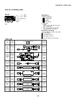
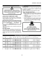
Controller application setting parameters
Para-
Controller
Min.
Max.
Factory
Actual
Setting and read-off parameters
meter
application no.
value
value
setting
setting
codes
1
2
3
4
1
) The compressor relay closes when the room temperature exceeds
the setting value and differential.
2
) Alarm is released and sensor failure is indicated, if the room
temperature reaches 5
°
C or more outside the setting range
–60
°
to +50
°
C.
3)
The frequency is measured after approx. three days and
nights operation after start of the plant (72 cyclings)
otherwise:
ON-time = c03
×
20: 100 minutes
OFF-time interval 20 minus ON-time per minute
4
) Function possibilities with SPDT contact, connected to the
terminals 3 and 4 are the following:
Door alarm: If SPST is cut out, alarm signalling starts and the fan is
stopped, cf. A04 or F02.
Defrost: If SPST is cut in, defrost starts. (However, if d03 is not OFF,
defrost will during contact break down start with the programmed time
intervalles).
Bus: With installed communication card, the position of the SPST
contacts will be registered in the BUS system.
Temperature controller,
Temperature
-60
o
C
50
o
C
3
o
C
Thermostat
Differential
1
)
r01
0.1 K
20 K
2 K
Max. limitation of set temperature
r02
-59
o
C
50
o
C
50
o
C
Min. limitation of set temperature
r03
-60
o
C
49
o
C
-60
o
C
Adjustment of temperature indication
r04
-20 K
20 K
0.0 K
Temperature unit (
°
C/
°
F)
r05
o
C
Alarm
Upper deviation (above temp. s differential
2
)
A01
0 K
50 K
5 K
Lower deviation (below temp. setting
2
)
A02
0 K
50 K
5 K
Temperature alarm delay
A03
0 min
90 min
30 min
Door alarm delay
A04
0 min
60 min
30 min
Compressor
Min. ON-time
c01
0 min
15 min
0 min
Min. OFF-time
c02
0 min
15 min
0 min
Cut-in frequency on sensor fault
3
)
c03
0 %
100 %
0 %
Defrost
Defrost method (EL/GAS)
d01
EL
Defrost stop temperature
d02
0
o
C
25
o
C
6
o
C
Interval between defrost starts
d03
OFF
48 hour
8 hour
Max. defrost duration
d04
0 min
180 min
45 min
Time staggening on defrost cut-ins at start-up
d05
0 min
60 min
0 min
Drip-off time
d06
0 min
20 min
0 min
Fan start delay after defrost
d07
0 min
20 min
0 min
Fan start temperature
d08
-15
o
C
0
o
C
-5
o
C
Fan cut-in during defrost (yes/no)
d09
yes
Defrost sensor (yes/no)
d10
yes
Temperature alarm delay after defrost
d11
0 min
199 min
90 min
Fan
Fan stop on compressor cut-out (yes/no)
F01
no
Fan stop delay
F02
0 min
15 min
0 min
Miscellaneous
Delay of output signal cancellation after start-up
o01
2 s
120 s
2 s
Digital input signals
4
)
(0 = not used, 1 = door alarm, 2 = defrost, 3 = bus)
o02
0
Real time clock (if fitted)
Six start times for defrost
All can be cut out by setting on OFF
t01
→
t06
0
23
OFF
Hour setting
t07
0 hour
23 hour
0 hour
Minute setting
t08
0 min
59 min
0 min
Fault code display
Alarm code display
Fault in controller
E 1
High temperature alarm
A 1
Disconnected room sensor
E 2
Low temperature alarm
A 2
Short-circuited room sensor
E 3
Door alarm
A 4
Disconnected defrost sensor
E 4
Status code display
Short-circuited defrost sensor
E 5
ON-time
S 2
OFF-time
S 3
Drip-off time
S 4
Содержание SCSS
Страница 22: ...IGSSB SCSS SCSS SL 0108 22 ...


