CRANKCASE
13
38
Main bearing
Tools
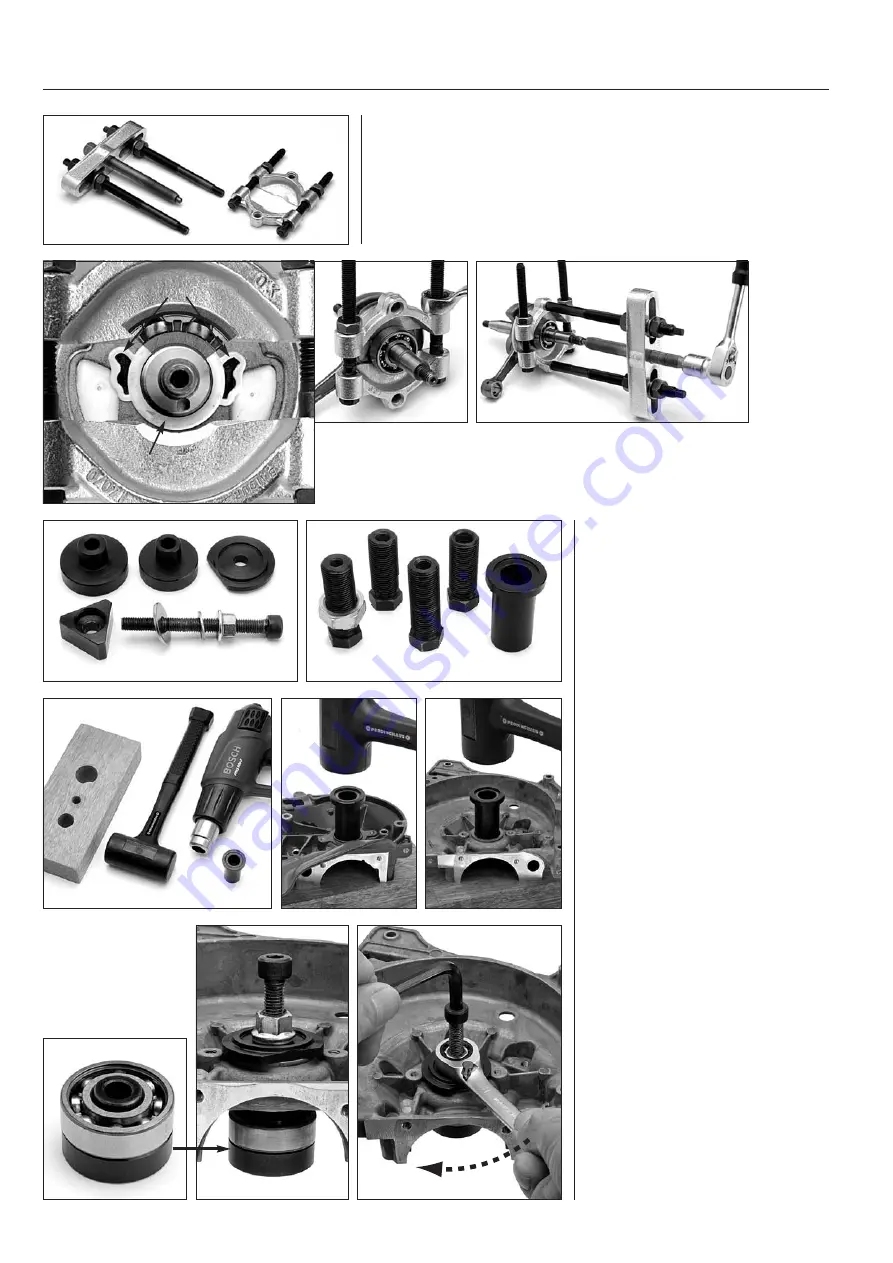
Use the tool kits opposite to change the
main bearing.
Dismantling
Note The tubular guides for the crank -
case halves must be removed!
Place the crankcase halves against a flat
piece of wood or the like. Heat around
the bearing with a hot air gun, max.
300 °F/150 °C. Place the sleeve in the
tool kit against the bearing and knock
this out with a large plastic mallet.
Assembly
Use the tool kit 506 37 61-02 for bearing
assembly in both crankcase halves.
Place the bearing on the support plate
and hold it under the crankcase half.
Insert the screw through the washer and
fit the screw in the support plate.
Lock the screw and turn the nut until
the bearing reaches the stop in the
crankcase half.
506 37 61-02
544 10 36-02
531 00 48-67
If the bearing releases from the crankcase
Normally the bearing should release from the crankshaft during dismantling.
The bearing is dismantled from the crankshaft using the puller 531 00 48-67.
1. First fit the puller plate behind the bearing. Exercise care so that the plastic
components on the balance weights are not damaged, see “IMPORTANT!”
2. Fit the puller unit and press the bearing off of the crankshaft.
A
B
1
2
IMPORTANT!
Turn the puller plate so that the “ears” (A) are free. The jaws must not be screwed
together further than to the centre ring (B), otherwise the plastic ring will be damaged.


