background image

AIR FILTER

8

17

Function

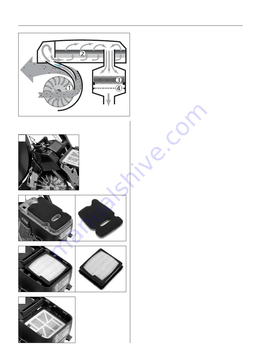
Husqvarna Active Air Filtration

is a filter system that 

effectively purifies the air to the engine in 

three separate steps

and according to three different purification principles:

1. Centrifugal cleaning 

is the first step in the purification of

the inlet air. 

The fins on the flywheel supply the cylinder with cooling air 

at the same time as they act as the active part in the centrifugal
cleaning of the engine's inlet air. An inlet nozzle is fitted close to
the fins on the flywheel. The centrifugal force means that large
particles do not follow the curved air currents to the nozzle, but
are thrown to the outside of the nozzle. Only very small dust 
particles manage to swing with the air currents to the inlet. 

2. Foam plastic filter 

is the next level of separation in the

purification process. An air deflector guides and distributes the
air across the whole filter surface, which means that the whole of
the filter is better utilised and is fouled evenly across the surface.
The filter is steeped in oil and is made up of three layers with 
different pore sizes. 

3. The paper filter 

primarily provides effective protection

should the foam plastic filter, on account of inadequate care, lets
dust through.

4. Service filter's 

sole task is to prevent foreign objects from

entering the engine during service work. The service filter should
only be replaced if it is damaged.

Filter service

Centrifugal cleaning

The inlet duct should be inspected and any deposits re moved 
in connection with filter replacement. Dust from dry cutting is
cleaned off using compressed air Material from wet cutting nor-
mally needs to be scraped off mechanically. Check that the seal
on the foam plastic filter's filter base is intact. Fit the seal correctly
in the air duct cover!

Foam plastic filter

New filters are supplied steeped in the correct amount of filter
oil. The replacement frequency is dependent on a number of fac-
tors and therefore cannot be generally stated. Unfortunately there
is no easy method to assess a used filter's remaining capacity, and
it is even harder when the machine's history is not known.
However, in all safety it can be said that if dust particles can be
discerned on top of the filter (clean side) it is spent. 

Paper filter

The paper filter should not be clean, but is replaced with a new
one. The replacement frequency depends very much on the care
of the foam plastic filter.

Exercise extreme care when the filter is dismantled so that dust

particles do not fall down through the service filter. Vacuum clea-
ning is the best method to remove spillage and to clean the gasket
around the service filter.

A useful rule for filter replacement is: Replace the paper filter

when the yellow paper colour is no longer visible.

2

3

4

502 53 08-26

Cylinder
cooling air

In

To carburettor

1

Содержание K 750

Страница 1: ...HUSQVARNA CONSTRUCTION PRODUCTS Workshop manual K 750 ...

Страница 2: ...ASIC MODULES 5 5 STARTER 9 6 IGNITION SYSTEM 12 7 FLYWHEEL 15 8 AIR FILTER 17 9 FUEL SYSTEM 18 10 CARBURETTOR 21 11 DECOMPRESSION VALVE 28 12 CYLINDER PISTON 29 13 CRANKCASE 35 14 CLUTCH 40 15 CUTTING HEAD 44 16 FRICTION RETARDER 49 17 HANDLE 51 18 TOOLS 52 CONTENTS Page HUSQVARNA K 750 502 53 08 26 ...

Страница 3: ...ng the speci fic service work Layout pictures and text Besides the pictures and illustrations there is generally two columns of text The left hand text column is a concise and is suitable for experienced mechanics the right hand column gives a more detailed description and is targeted at mechanics with less experience of repair work on the power cutter Contents The manual is divided into numbered ...

Страница 4: ...om EPAII The output is higher over the entire speed range and the torque in the lower speed range is now significantly higher Lower vibration levels The air filter system and the carburettor are mounted in the dampened handle unit which means lower vibration on the handle through the greater mass weight in the handle unit The carburettor placement in the dampened section results in stable carburet...

Страница 5: ...tarter 9 Combination spanner 10 Belt adjustment screw 11 Lock screws for belt adjustment 12 Cutting arm rear belt guard 13 Fuel tank 14 Throttle control 15 Rear handle 16 Throttle trigger lock 17 Water valve with tool attachment 18 Water connector 19 Choke Lever 20 Sight glass for fuel 21 Start throttle lock 22 Stop switch 5 4 1 2 3 6 7 8 9 10 11 13 12 14 17 18 19 15 16 22 21 20 ...

Страница 6: ...ective chapters Cutting arm 1 Loosen the screws on the cutting head 2 Slacken off the belt tension using the adjuster screw Dismantle the screws on the cutting head 3 Dismantle the front belt cover by sliding it forwards 4 Loosen the hoses by the water valve Lift off the belt from the pulley and remove the cutting head 5 Loosen the two screws on the rear belt guard Tightening torque when assemblin...

Страница 7: ... lifted off 2 NOTE When reassembling the rubber seal must be drawn up through the cover and the collar then adjusted to fit correctly against the cover Carburettor 1 The carburettor unit is attached to the cylinder by a single screw Loosen the screw 2 Lift up the carburettor unit Loosen the fuel hose arrow from the carburet tor Tip Tape the throttle control in the full throttle position to improve...

Страница 8: ...This is dismantled by angling the unit backwards and then pulling it out the tank 2 Stop switch This is secured by a screw in the carburet tor compartment 3 Controls The controls in the rear handle become accessible for service once the carburettor unit has been dismantled Air duct First dismantle the starter 1 Lower air duct Note to facilitate reassembly how the cable to the stop switch is fitted...

Страница 9: ...the machine by the vibration dampe ning element Dismantle the air filter unit cylinder cover and upper the air duct cover Dismantle the screw holding the carbu rettor Dismantle the starter and the air duct cover Loosen the cable lug by the ignition module and unscrew the cable to the earth point Pull off the water hose by the valve The engine unit is attached to the handle unit at three points wit...

Страница 10: ...tarter pulley Attach the new starter cord The starter cord should be 45 in 115 cm long and have a diameter of 16 in 4 mm 1 Insert one end of the cord from the top through the hole in the starter pulley and then out through the notch for the cord Pull out virtually the whole cord length until sufficient cord remains to tie a knot as illustrated 2 Insert the other end through the cover and on throug...

Страница 11: ...light oil on the spring Starter pulley Dismantle the centre bolt and lift off the starter pulley Clean the surfaces between the starter pulley and the spring cassette Assembly Lubricate the hub with grease arrows Preferably also apply some grease around the starter pulley hub so that the grease seals against the spring cassette Align the starter pulley cut out with the end of the spring when assem...

Страница 12: ...washer A that should lie under the starter pawls against the flywheel Assembly It is important that the spring does not get caught between the starter pawls and the flywheel The following method is recommended when assembling 1 Press the spring into position in the flywheel 2 Fit the washer 3 Screw on the starter pawls 4 Make the simplest of special tools Bend the end of a thin steel wire and use ...

Страница 13: ...g Electronic circuit breaker STOP control Volts 0 Ignition point S N S N 1 1 A D B C 2 2 3 3 Ignition module Individual components can not be replaced The ignition lead contact unit to the spark plug and seals on the ignition module can be replaced The ignition module requires no periodic servicing Neverthe less the distance to the flywheel s magnet may need adjusting The short circuit contact arr...

Страница 14: ...ignition lead Faulty ignition lead 1 2 Pull up the rubber seal by the igni tion module and unscrew the ignition lead from this 3 Insert a pair of pointed pliers in spark plug connection and pull out the spring and cable end 4 If the connection is defective the igni tion lead can be shortened slightly Make a new hole in the cable with a awl and fit the connection spring 5 The adjoining simple conne...

Страница 15: ...st the function of the stop switch Test with a test lamp Connect a battery in series with a test lamp to the short circuit cable respective engine body With the stop switch in the ope rating position the lamp should not be lit Look at the test lamp while you move the cable in different positions respective test the stop switch Test with a meter Connect the instrument to the short circuit cable res...

Страница 16: ...al tool to lock the rotation of the flywheel and dismantle centre bolt Dismantle the nut Press off the flywheel Fit the screw puller in the centre and screw it down as far as necessary to get a secure fitting in the plate Hold the large nut and screw in the centre bolt until the flywheel releases Tip If the flywheel is very tight knocking the bolt lightly with a hammer to help the flywheel to rele...

Страница 17: ...e right placement in relation to each other Only the force of the centre nut is not sufficient to hold the flywheel in the right position Fit the flywheel The crankshaft and the centre of the fly wheel must be free from grease when assembling Align the key in the flywheel with the keyway on the crankshaft Fit the washer and centre nut Tightening torque 18 22 lbf ft 25 30 Nm Use a torque wrench to ...

Страница 18: ... the engine during service work The service filter should only be replaced if it is damaged Filter service Centrifugal cleaning The inlet duct should be inspected and any deposits removed in connection with filter replacement Dust from dry cutting is cleaned off using compressed air Material from wet cutting nor mally needs to be scraped off mechanically Check that the seal on the foam plastic fil...

Страница 19: ...laced with new ones Heavily fouled filters can be due to fuelling with contaminated fuel Check and filter the fuel if necessary Fuel hose Pressure tester 501 56 27 01 Use the pressure tester 501 56 27 01 to test the tightness of the fuel hose The pressure tester is supplied with an adapter for small hose sizes this should be used on the fuel hose Make the hose between the adapter and the pressure ...

Страница 20: ...by little The new hoses is fed down into the tank from the carburettor compartment Feed down the hose by hand or with the help of a pair of pliers Greasing the hoses facilitates assembly Changing the fuel hose Loosen the cable lug to the stop switch Remove the hose from the tank at the same time as it is fed down through the hole in the carburettor compartment Fit the hose in the same direc tion b...

Страница 21: ...rn valve to pressure tester 501 56 27 01 Note Never expose the non return valve to a high pressure compressed air Test the non return valve by first blowing in the direction towards the tank The air should pass without a build up of pressure Blow in the direction towards the filter The non return valve should stop a pres sure of approximately 3 6 psi 20 40 kPa At a higher pressure the non return v...

Страница 22: ...eaked in Clean the carburettor unit Work on the carburettor requires extreme cleanliness Start work with by carefully cleaning the outside with compressed air The carburettor is secured on the inlet bracket by four screws Remove the screws Clean the carburettor unit Carefully clean the outside first Dismantle the carburettor from the bracket Note the gasket between the carburettor and the inlet br...

Страница 23: ...horten the life of the engine Assembly Push in the rubber guides past their seatings on the plate Now pull out the guides one at a time into their correct position Fit the support insert Parts must face the right way Note that the guide to the inlet is slightly bevelled on one edge Turn the bevel towards the fuel air inlet Parts must face the right way Note that the guide to the inlet is slightly ...

Страница 24: ...lve if the work demands this Dismantling assembling Dismantling the air valve The air valve is secured on the carburet tor by two screws The air valve does not need to be dis mantled to check the function of the carburettor or for most service work However dismantling the air valve facili tates accessibility Link rod Note the attachment of the link rod when reassembling Link rod Note the attachmen...

Страница 25: ...ine Connect a thin short hose to the carburettor s fuel pipe Pump a pressure to 15 36 psi 100 250 kPa the needle valve should then lift Air bubbles then come out of the jets in the venturi The pressure should then drop to approxi mately 15 7 psi 100 50 kPa and then drop significantly slower or stop com pletely Pressure drop after 7 psi 50 kPa indicates a leaking needle valve If the needle valve do...

Страница 26: ...iaphragm Make a visual inspection of the diaphragm with regard to cracks and leakage Fuel on the top towards the cover indicate leakage Change the diaphragm Check that the spring is intact and that the lever runs easily on the axle Check that the spring is intact and that the lever runs easily on the axle Inspect the tip of the needle with a magnifying glass If there are signs of deposits that can...

Страница 27: ...s previously described The function of the valve flaps cannot be pressure tested and must be visually inspected The valve flaps must be absolut ely flat and close tight against the carburettor housing Fuel strainer There is a fine meshed strainer located on the fuel inlet to the carburettor Inspect this with a magnifying glass Loose dirt particles can be blown away from the needle valve s seating ...

Страница 28: ...eed If the blade rotates lower the speed a little If this does not help the clutch should be rectified Adjust outdoors Naturally the idle speed must be adjusted outdoors The blade should be fitted Run the machine warm for approximately 5 minutes Keep the instrument with the arrow directed downwards towards the position of the spark plug Adjust the idle screw to an idle speed of approximately 2700 ...

Страница 29: ...ssion valve can easily be checked for leakage without starting the machine Use a leakage spray or soapy water Move the stop button to the stop position and slowly pull the starter handle while observing the decompression valve Assembly Clean the sealing washer and check that this is not damaged before assembling the the decompression valve Leakage test Use a leakage spray or soapy water Move the s...

Страница 30: ... the decompression valve as the source of the fault Compression tester The compression test is performed using the measurement instrument 531 03 16 86 which is connected to the spark plug hole The valve below the gauge evacuates the pressure Compression tester Connect the compression tester in the spark plug hole Compression test Run the engine warm for a few minutes Unscrew the spark plug and con...

Страница 31: ...en the piston and the crankcase to facilitate the work Tool kit 502 50 70 01 The tool kit contains piston ring compressors a piston stop and a support plate for the piston The piston stop must not be used on K750 Remove the cylinder base gasket Seal with a cloth or paper so as not to risk anything falling down into the crankcase Seal with a cloth or paper so as not to risk anything falling down in...

Страница 32: ...the ring and move it away from you so it can be lifted out of the groove at the rear edge Assemble the parts in the reverse order Piston rings Dismantle the piston rings Important when assembling The piston ring groove has a guide pin that prevents the piston rings from rota ting Fit so that the open part of the piston ring aligns with the guide pin Turn the piston ring with the bevelled edge towa...

Страница 33: ...n com pletely smooth by the ports you should consider replacement Piston ring groove Measure the piston ring groove using feeler gauges If the piston ring groove is greater than 06 in 1 6 mm the piston must be replaced Fit a complete piston kit with piston rings needle bearing and gudgeon pin Piston ring groove If the piston ring groove is greater than 06 in 1 6 mm the piston must be replaced Fit ...

Страница 34: ...e this results in a lean fuel air mixture which first and foremost give scoring on the exhaust side Look for combination effect as in the example below Overheated piston top Clear signs of overheating are aluminium deposits on the top of the piston which in extreme cases can result in melting Excess air in relation to the fuel volume increases the tempera ture in the combustion chamber Therefore c...

Страница 35: ...m the surfaces that connect with the gasket Fit the gasket on the cylinder Cylinder base gasket Carefully clean off any old gasket residue from the surfaces that connect with the gasket Fit the gasket on the cylinder Assemble the cylinder Check that the opening on the piston rings align with the guide pin Assemble the cylinder Check that the opening on the piston rings align with the guide pin Pre...

Страница 36: ...nel on the crankshaft Does not apply to machines with bearing mounted clutch drum Inlet port 3 Loosen the screws on the carburettor s lower mounting a few turns 4 Position the inlet seal and fit the screw Tighten the lower mounting with care so that the clamp is not deformed Fit the sealing plug in the hole in the cylinder for the decompression valve Test for leakage Connect the pressure tester on...

Страница 37: ... flywheel side Assembly CLUTCH SIDE 1 Lubricate the assembly taper and place on the axle 2 Press down the sealing ring over the taper and down towards the seating 3 Knock down the sealing ring into its seating with the assembly punch Assembly FLYWHEEL SIDE 1 Lubricate the axle The assembly taper is not used 2 Press the sealing ring against the seating 3 Knock down the sealing ring into its seating...

Страница 38: ...k can be removed and replaced These are important for the function of the engine and must not be forgotten when reassembling Connecting rod Check that there is no radial play on the connecting rod by the crankshaft journal Clean the gasket surfaces Carefully clean the gasket sur faces Filled balance weights The balance weights on both sides of the crank can be re moved and replaced Crankcase Tools...

Страница 39: ...through the washer and fit the screw in the support plate Lock the screw and turn the nut until the bearing reaches the stop in the crankcase half 506 37 61 02 544 10 36 02 531 00 48 67 If the bearing releases from the crankcase Normally the bearing should release from the crankshaft during dismantling The bearing is dismantled from the crankshaft using the puller 531 00 48 67 1 First fit the pull...

Страница 40: ... the crankcase half Make sure that the connecting rod is not held against the crankcase half Picture 5 Fit the guides Picture 6 Fit the new crankcase gasket Picture 7 Assemble the other crankcase half using the same method as the first Change to the other threaded mandrel IMPORTANT Pay attention to the position of the connecting rod while tightening so that this does not get jam med in position Al...

Страница 41: ...clutch drum Note the washer between the clutch and the drum Reassembly Note that the clutch should be turned with the low spanner grip towards the clutch drum The clutch should be tightened to a torque of 27 32 lbf ft 37 43 Nm Wear tolerances Engagement speed min 3100 rpm The clutch must be rectified if the blade starts to rotate at an engine speed below 3100 rpm Clutch shoes The height of the clu...

Страница 42: ...all bearing has a loose sealing washer Dismantling Dismantle the support ring using a universal puller Assembly The support ring is assembled using the tool intended for assembling the crank shaft in the crankcase 544 10 36 02 Fit the piston stop 504 91 06 05 Position the support ring on the axle and position the tool as illustrated Assembly Fit the support ring with the tool intended for assembli...

Страница 43: ...aring with the help of socket 29 32 in 23 or 24 mm M8 screw approximately 3 4 in 80 mm and nut washer outside diameter slightly smaller than 3 4 in 19 mm washer diameter approximately 1 1 4 16 in 25 30 mm Bearing replacement needle bearing For a long time a clutch drum with needle bearing has been the standard design on Husqvarna petrol driven power cutters The needle bearing is lubricated via a c...

Страница 44: ... also have a washer between the clutch drum and clutch Tools The tool kit 504 56 79 01 is needed to replace the ball bearing of the clutch drum Use the tool to dismantle and fit the bearing as described below The tool kit consists of a support plate for the bearing A the sleeve B and the cover C Note that the cover has different profiles one side to match the sleeve on dismantling and the other to...

Страница 45: ...with the bearing seal Check that the seal is intact Dirt under this indicates defective seals and these should be replaced Remove the spacer together with the bearing seal Check that the seal is intact The washer and the three screws hold the blade guard against the bearing housing Remove the screws and the washer Remove the screws that hold the blade guard against the bearing housing Remove the w...

Страница 46: ... 02 Bearing replacement Tools To replace the blade shaft bearing a special tool is needed 506 37 61 02 Use the tool both for dismantling and assembly The tool s round threaded plate is the support plate for the bearing that is to be fitted Use the plate with the smaller diameter for the K750 Use the round chamfered washer when assembling the inner bearing Use the triangle when assembling the outer...

Страница 47: ...f both bearings Alternatively a brass punch can be used to drive out the axle Split the bearing unit Use the vice as a counterhold Fit the screw on the special tool in the axle and knock the axle out of both bearings Alternatively a brass punch can be used Check Check that the axle and the bearing seating in the cutting arm are not damaged If the bearing is seriously damaged so that it has been sc...

Страница 48: ...first Pull in the outer bearing until the spacer ring touches 1 Assembling the axle First check that the spacer ring between the bearings is centred The following procedure gives good results Turn the triangle with the smooth side facing downwards Hold the axle on its underside and screw in the screw of the tool along with the large washer Note that the triangle lies directly against the bearing f...

Страница 49: ...ring housing blade guard Check that the rubber seal is fitted properly against the bearing housing and blade guard Turn the bearing housing so that the screw hole becomes accessible from the top with the tool Tighten the three screws crosswise so that the washer is not unevenly loaded and risks being deformed Tighten the screws fully Fit the seal with spacer ring Centre bush Never hit the centre b...

Страница 50: ...e held together by the spring In the event of replacement replace the entire unit as in the picture The brake drum is fitted against the bearing housing with three screws The centrifugal unit is secured against the belt pulley with four screws Dismantling Procedure To be able to handle the friction retarder as a single coherent unit it is important that dismantling and assembly are carried out in ...

Страница 51: ...ee screws Assembly of the centrifugal unit Normally the unit is handled without dismantling it If needed carry out assembly of the parts in the following manner 1 Place the spring in position in the guide plate Note where the spring ends should be located 2 Locate the brake drum in its position 3 Assemble the brake shoes by stretching the spring with a screwdriver and then locating the brake shoe ...

Страница 52: ...lty function must be rectified The carburettor unit must be dismant led to carry out a service on the controls Dismantle the starter Drive mandrels with dimensions under 3 mm are usually too short for dismant ling the throttle spindle Use a round rod instead with a diameter of 08 01 in 2 2 5 mm and approximately 4 in 10 cm in length Dismantle the starter Use a round rod with a diameter of 08 01 in...

Страница 53: ...re tester Test of carburettor functionality Test of fuel lines Test of non return valve in the tank ventilation 503 55 22 01 Sealing plug Replaces the decompression valve Included in 544 10 33 01 Leakage testing the crankcase 502 50 70 01 Kit for piston service Consisting of piston ring compres sor piston stop and support plate Use piston stop 504 91 06 05 for K750 Piston service 504 91 06 05 Pist...

Страница 54: ...kcase in com bination with 504 90 90 02 531 00 48 67 Bearing puller Dismantling the main bearing from the crankshaft 544 10 36 02 Bearing press Dismantling the main bearing Assembly of the crankshaft Assembly of the clutch s support washer on the crankshaft 502 50 83 01 Hose catcher Tool for catching the fuel hose in the tank and drawing out the fuel filter for servicing Fuel filter and hose 501 6...

Страница 55: ...www husqvarnacp com 502 53 08 26 English 2007 06 ARNE PALMQUIST ...

Отзывы: