6.
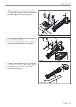
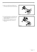
Separate the contacts (A-A) and (B-B).
7.
Extend the cables (A) and (B) with approximately 90
cm long steel wires attached to the contacts. This
makes it easier to draw the cables to the new
heating element back through the handle.
1 = black
2 = blue
See figure 3.
8. Remove the bolt that holds the left grip on the
handle.
9. Pull out the handle from the handlebars
10. Pull out the cables carefully and one at a time, so
that the steel wire does not come loose from the
cables.
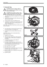
11. The heating element is located in a pocket in the
outside of the handle. Use flat-nosed pliers to pull
out the heating element from the handle.
See figure 4.
CAUTION: Do not pull the cables or their
connections.
Assemble in the opposite sequence as for dismantling.
CAUTION: Do not pry off the heating
element before the locking catch has been
removed. The element can get damaged.
Engine
Heater
box
Right
handle
Left
handle
AT2 module
Carburettor
HT cable
Ignition module
Generator
JST connector
Molex Microfit connector
1-pol connector
Heater
RX
1
Heat switch
OFF-ON
1
2
S2
Heater
RX
2
Stop
switch
OFF-ON
S1
G
Blue
Blue
Black
Red
Red
Black
Blue
Blue
Black
Red
1-pol connector
1
2
Electric schematic 545FXT-AT
Fig. 3
Fig. 4
English – 19
Содержание 545FX AT
Страница 1: ...Workshop manual English 545RXT AT 545FX AT 545FXT AT 545FX 545FXT 545RX 545RXT ...
Страница 2: ......
Страница 8: ...Service tools 3 Service tools 3 mm 4 mm 5 mm 1 11 4 6 9 7 10 8 5 2 12 3 13 14 15 16 17 8 English ...
Страница 79: ...English 79 ...
Страница 80: ...2018 10 04 115 88 11 26 ...


