20
DISASSEMBLY
1. Tool
Refer to tool replacement procedures (Figure 4, Page 12).
2. Back
cap
Support the cylinder (Figure 12). Loosen and remove four side rods and washers,
then remove the back cap.
3. Front cap
(See Table 3 page 14 for eyebolt sizes)
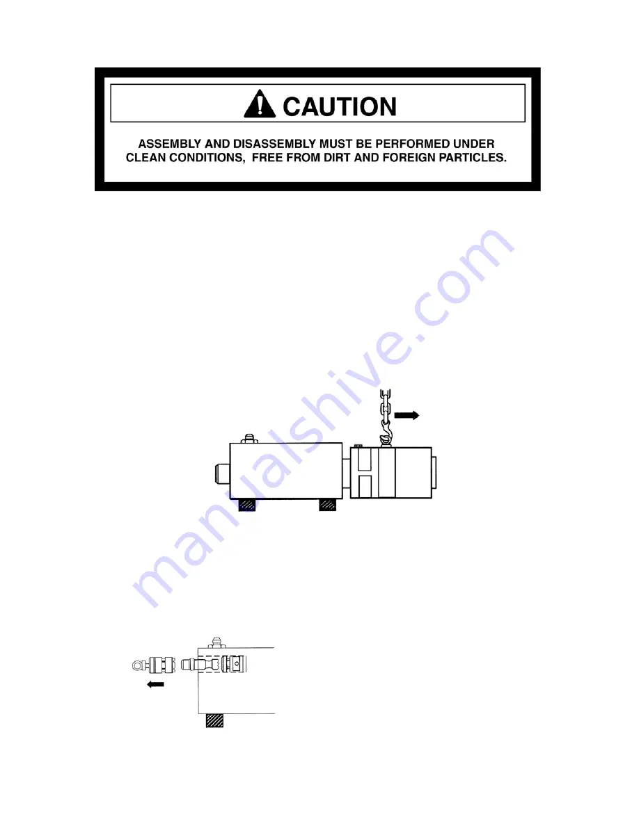
Install an eyebolt and suspend the front cap as shown in Figure 12. Pull out the front
cap, being careful not to damage the piston.
Figure 12. Connecting Hoist to Front Cap.
4. Main
valve
Attach an eyebolt to outer sleeve and remove it by pulling the eyebolt. (Figure 13.)
Remove the main valve. The inner sleeve cannot be removed, it is press fitted and
requires a special tool. Contact the factory for further details.
Figure 13. Removing the Main Valve
Содержание HH100
Страница 1: ...HUSKIE HYDRAULIC HAMMERS SERVICE MANUAL HH100 HH150 2 HH300 2 HH500 2 HH750 2 HH1000 2 ...
Страница 2: ...2 ...
Страница 33: ...33 9 PARTS LIST AND ILLUSTRATIONS HH100 HH150 2 HH300 2 HH500 2 HH750 2 HH1000 2 ...
Страница 35: ...35 HH100 HAMMER Effective 07 09 ...
Страница 37: ...37 ...
Страница 39: ...39 HH150 2 HAMMER S N 001 099 2B2 1000 UP Effective 07 09 ...
Страница 41: ...41 ...
Страница 43: ...43 HH300 2 HAMMER S N 001 099 2E2 1000 UP Effective 07 09 ...
Страница 47: ......
Страница 49: ...49 HH500 2 HAMMER S N 001 099 2R2 1000 UP Effective 07 09 ...
Страница 55: ...55 HH750 2 HAMMER S N 001 099 2F2 1000 UP Effective 07 09 ...
Страница 59: ...59 ...
Страница 61: ...61 Effective 07 09 HH1000 2 HAMMER S N 001 099 2H2 1000 UP ...


