background image

To mount the transducer bracket to the boat:

1.  Remove the transducer mounting template from this manual. (See 

Appendix A,

Transducer Mounting Template: SHS 7W

). 

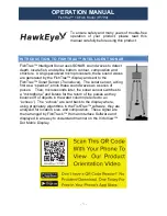
2. Hold the template on the transom of the
boat in the location where the transducer
will be installed. Align the template
vertically, matching the lower edge of the
transom with the bottom corner of the
template. If your propeller moves
clockwise as the boat moves forward,
mount the transducer on the starboard
side, and use the bottom left corner of the
template. If your propeller moves counter-
clockwise as the boat moves forward,
mount the transducer on the port side, and
use the bottom right corner of the
template. 

3.  Using a pencil or punch, mark the three mounting holes on the transom. Do not

mark or drill any other holes at this time.

4.  Using a 5/32" (4.0 mm) bit, drill the three holes to a depth of approximately 

1" (25 mm). On fiberglass hulls, it is best to use progressively larger drill bits to
reduce the chance of chipping or flaking the outer coating. Use a marine-grade
silicone sealant to fill the drilled holes.

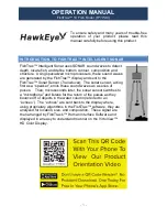
5. Align the metal mounting bracket with the
mounting holes. The center slot should be above the
two outer slots. (This bracket and all other hardware
supplied is top quality stainless steel for maximum
strength and corrosion protection.) Insert the three 1"
(25 mm) flat head wood screws into the drilled holes,
but do not completely tighten. 

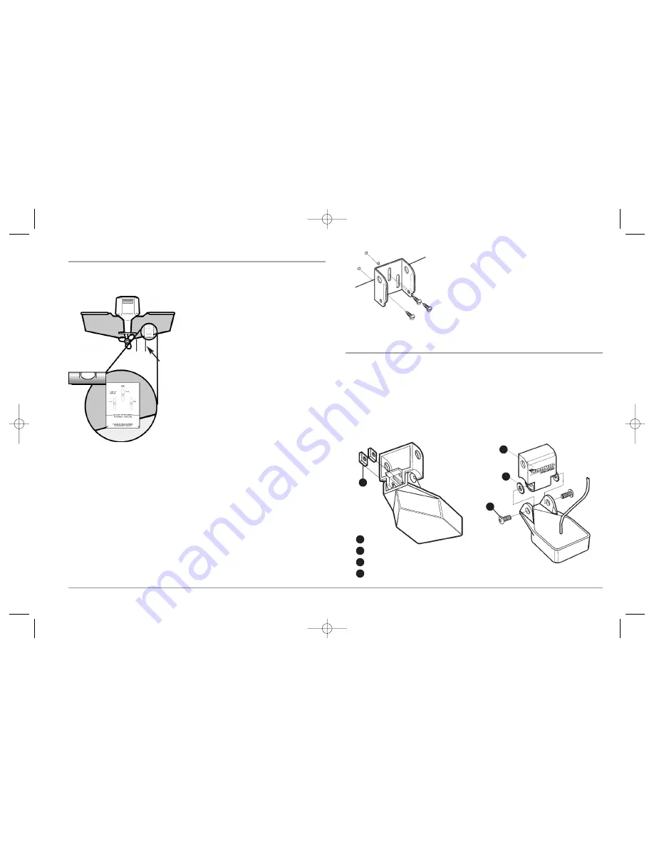
To attach the pivot to the transducer:

1. Attach the pivot to the transducer body, using the two 1/4"-20 x 5/8" (16 mm)

machine screws, toothed washers, and square nuts. The toothed washers must
fit on the inside of the transducer ears, between the pivot and the ears. The
square nuts will be prevented from rotating by the pocket in the back of the
pivot. An Allen wrench is provided which fits all the 1/4"-20 screws, but do not
fully tighten the screws at this time.

Pivot

1

Toothed Washer

2

Machine Screw

3

Square Nut

4

Insert the Square Nuts

Attach the Pivot

1

2

4

3

Attaching the Bracket

Level

15” (380 mm)

from prop(s)

12

531374-1_A - 947 Man.qxd  2/15/2005  7:53 PM  Page 17

Содержание 947C

Страница 1: ...531374 1_A 947 Man qxd 2 15 2005 7 52 PM Page 1...

Страница 2: ...be used as a navigational aid to prevent collision grounding boat damage or personal injury When the boat is moving water depth may change too quickly to allow time for you to react Always operate the...

Страница 3: ...ry Installation 21 Testing the System Installation 22 Getting Started Using Your 900 Series 23 Powering Up the Control Head 23 What s on the 3D Sonar Display 24 What s on the 2D Sonar Display 25 Real...

Страница 4: ...54 Save Current Route Only when navigating 54 Skip Next Waypoint Only when navigating 54 Cancel Navigation Only when navigating 55 Remove Target Only if a Target is active 55 Remove Grid Only if a Gri...

Страница 5: ...Time Advanced 75 Position Format Advanced 76 Time Format Advanced International only 76 Date Format Advanced International only 76 NMEA Output Advanced 76 Sonar 77 Views Menu Tab 77 Accessories Menu T...

Страница 6: ...creased sonar resolution although the distance depth a high frequency signal can travel is relatively short A low frequency signal can travel great distances but provides poor sonar resolution The sha...

Страница 7: ...h a built in World map with a more detailed map of North America Domestic models or a more detailed map of Europe and Southeast Asia including Australia and New Zealand International models Your 900 S...

Страница 8: ...SmartCast Wireless Sonar Link require separate purchases You can visit our website at www humminbird com or contact our Customer Resource Center at 1 800 633 1468 for additional details INSTALLATION O...

Страница 9: ...00 633 1468 CONTROL HEAD INSTALLATION You have two choices for mounting your 900 Series control head Gimbal mounting where you use a surface on the boat such as the dash to mount the control head so t...

Страница 10: ...l bits to reduce the chance of chipping or flaking the outer coating Fill all holes with marine grade silicone sealant NOTE Youmusthaveundersideaccesstothemountinglocationtopassthecablesthroughto the...

Страница 11: ...rill the two mounting holes using a 9 64 3 5 mm bit fill them with marine grade silicone then replace the hole cover and insert the 8 Phillips countersink wood screws Hand tighten only 7 Place the mou...

Страница 12: ...nectors into the wrong sockets Once the cable collector and all cables are plugged into the back of the control head lock the assembly into place by threading the knurled screw into the threaded inser...

Страница 13: ...In Dash paper template to the desired in dash mounting location 3 At a location inside the dotted line on the template drill a hole large enough to insert blade of reciprocating saw Carefully begin cu...

Страница 14: ...Plug the cable collector assembly into the back of the control head Cable connectors and cable sockets are keyed to prevent reverse installation so be careful not to force the connectors into the wron...

Страница 15: ...erent installation methods for your transducer Transom Transducer Inside the Hull Transducer Trolling Motor Transducer Find the section that describes the method of installation you will be using NOTE...

Страница 16: ...nter clockwise Thisturbulentwaterisnormallyconfinedtoareasimmediately aft of ribs strakes or rows of rivets on the bottom of the boat and in the immed iate area of the propeller s Clockwise propellers...

Страница 17: ...reduce the chance of chipping or flaking the outer coating Use a marine grade silicone sealant to fill the drilled holes 5 Align the metal mounting bracket with the mounting holes The center slot sho...

Страница 18: ...r as described in the following paragraphs Further adjustment may be necessary to refine the installation after high speed testing NOTE Your transducer may not look exactly like the transducer shown i...

Страница 19: ...r cable up to a total of 50 15 m For assistance contact the Customer ResourceCenteratwww humminbird comorcall1 800 633 1468formoreinformation NOTE Sincethetransducermayneedtopivotupto90degreesinthebra...

Страница 20: ...find the best location Observe the outside of the boat hull to find the areas that are mostly free from turbulent water Avoid ribs strakes and other protrusions as these create turbulence As a general...

Страница 21: ...tionof the transducer route the cable from the transducer to the control head Permanently mount the transducer 1 Make sure the position of the transducer is marked 2 Remove the water from inside the h...

Страница 22: ...with the boat in the water although you can initially confirm basic operation with the boat out of the water NOTE If you have installed an in hull mount transducer this procedure does not apply as th...

Страница 23: ...TEM Follow these steps to stem mount the GPS receiver NOTE If you have an existing stem for mounting the GPS receiver proceed directly to step 2 of the following procedure 1 Determine the best locatio...

Страница 24: ...cable from the mounting location to the control head NOTE Installation details may vary with unit configuration 2 Markthemountinglocationanddrilla3 4 19mm holeforthecableandcable plug Route the cable...

Страница 25: ...t to the intended cable route 4 With the cable routed position the GPS receiver in the planned mounting location and mark the mounting holes with a pencil or punch 5 Move the GPS receiver to the side...

Страница 26: ...lls itisbesttostartwithasmallerdrillbitanduseprogressively larger bits to reduce the chance of chipping or flaking the outer coating Drill a 1 8 3 mm mounting hole approximately 3 4 19 mm deep 4 Seal...

Страница 27: ...menu Use the UP or DOWN 4 WAY Cursor keys to position the cursor then the RIGHT Cursor key to select System Status from the Start Up Options menu see the Start Up Options Menu section for more informa...

Страница 28: ...ING UP THE CONTROL HEAD Turn on your 900 Series control head by pressing the POWER key The Title screen is displayed until the 900 Series begins operation Your 900 series will begin Normal or Simulato...

Страница 29: ...nput or GPS Receiver 4 2D SonarView traditional2Dsonarfortheidentificationofstructureandbottomhardness 8 Boat DirectionArrow Asimple solid3DboatisdrawnwhentheUpperDepthRangeis0 A solid 3D arrow is dra...

Страница 30: ...GPS Receiver 3 Average Speed Average speed reading with Speed accessory or GPS Receiver 4 Thermoclines layers of water with different temperatures that appear at different depths and different times o...

Страница 31: ...ottoms typically will be displayed with red and softer bottoms typically will be displayed with blue The sonar returns from the bottom structure and fish can be represented as either Structure ID orWh...

Страница 32: ...key Thiswillensurethat shutdown occurs properly and any menu settings will be saved VIEW KEY The VIEW key is used to cycle through all available views Press the VIEW key to advance to the next view Re...

Страница 33: ...seanyarrowkeytochangetheperspectiveinthe3DSonar View Subsequent presses of arrow keys rotate and tilt the 3D representation VIEW PRESET KEYS The VIEW PRESET keys are used to program your three favorit...

Страница 34: ...or ZOOMkeyswhileinanyoftheNavigationViewsorthe Sonar Zoom View to change the scale of the view to appear closer or farther away VIEWS The views available on your 900 Series are Sonar views Navigation...

Страница 35: ...understanding the terrain beneath the boat The boat icon represents the location of your boat in relation to the on screen information The most recent sonar returns are charted on the upper right side...

Страница 36: ...ure and bottom hardness NOTE If the Depth number is flashing it means that the unit is having trouble locating the bottom Thisusuallyhappensifthewateristoodeep thetransducerisoutofthewater the boat is...

Страница 37: ...cornerandcanbechangedtosuitconditions see2D Sonar X Press Menu Zoom Level Upper and Lower Zoom Depth Range numbers indicate the depth of the water which is being viewed FreezeFrame Pressinganyarrowont...

Страница 38: ...w of the track and the chart land contour from a point above and behind the boat the eye point As the boat turns the eye point moves to follow the boat Big Digits on this view provide digital data in...

Страница 39: ...y or breadcrumb trail showing where the boat has been along with saved tracks waypoints and the current route when navigating are overlaid on the chart Youcanusethe4 WAYCursorControlkeytoshift panthec...

Страница 40: ...dastheactiveside see2DSonarX Press Menu Active Side or Navigation X Press Menu Active Side for more information A greenarrowpointstothesidethatisactive Youcanalsoadjustthesizeoftheleftside of a split...

Страница 41: ...ven if the boat is off the screen At the same time a cursor dialog box is displayed at the top of the screen with the distance and bearing from the boat to the cursor position and the latitude longitu...

Страница 42: ...sentedthatshowthetime direction andflowspeedofthecurrentchangesforthe24hourtimeperiodoftoday sdate You can change the date to look at current information before or after the date displayed bypressingt...

Страница 43: ...name and select an icon to represent it see Waypoint submenu on the Navigation Main Menu Tab DisplaytheWaypointsSubmenu Fromanyview presstheMENUkeytwicetodisplay the Main Menu System then use the RIGH...

Страница 44: ...GHT Cursor key Canceling navigation removes the route and any waypoints created using the GOTO key but does not remove any saved routes from memory You will be prompted to save the current route when...

Страница 45: ...submenu select Create and press the RIGHT Cursor key ARouteEditscreenwillbedisplayedwithanemptyroute Youcannametheroute add waypoints to the route from the list of all waypoints and order the waypoint...

Страница 46: ...ck FromtheTrackssubmenu selectDeleteandpresstheRIGHTCursor key to display the list of saved tracks Select the track you want to delete and press the RIGHTCursorkey Youwillbeaskedtoconfirmdeletionbefor...

Страница 47: ...An Advanced Mode is provided for users who desire the highest level of control over the 900 Series and Normal Mode for users who desire greater simplicity and fewer menu choices Additional Advanced m...

Страница 48: ...tatus See the following paragraphs for more information about each of these choices NORMAL OPERATION Use Normal operation for on the water operation with a transducer connected In addition your900Seri...

Страница 49: ...the Start Up Options menu allows you to pre configureyour900Series foron the wateroperation Anymenuchangesyoumakewillbe saved for later use A Simulation message will appear on the display periodicall...

Страница 50: ...is being monitored but is not yet being used This view also reports the current position local time and date and other numeric information ThecurrentGPSFixTypeisreportedasNoFix 2DFix 3DFix orEnhanced...

Страница 51: ...enu choice is only available when a Combo View is active To select the Active Side 1 Highlight Active Side on the 2D Sonar X Press Menu 2 Use the RIGHT 4 WAY Cursor Control key to change which side is...

Страница 52: ...TheUpperRangemenu choice is available when User Mode is set to Advanced see Setup Menu Tab User Mode andcanonlybeaccessedfromthe2DSonarView or3D 2DComboViewwhen the 2D Sonar side is active Upper Rang...

Страница 53: ...einformationintheSonarViewsandispreferredby most anglers however the sonar information moves across the display quickly A slower speed keeps the information on the display longer but the bottom and fi...

Страница 54: ...ed 10 60 feet 2 10 fathoms or 3 20 meters International Models Only Default 15 feet 2D 3D PRIORITY 2D 3D Priority allows you to change the way the 6beamsonthetransducerareusedinordertoprioritizeandcus...

Страница 55: ...choice is only available when a Combo View is active To select the Active Side 1 Highlight Active Side on the 3D Sonar X Press Menu 2 Use the RIGHT 4 WAY Cursor Control key to change which side is ac...

Страница 56: ...o View Use 3D Bottom Zoom to increase the detail of the bottom on the display To adjust the 3D Bottom Zoom 1 Highlight 3D Bottom Zoom on the 3D Sonar X Press Menu 2 Use the LEFT or RIGHT 4 WAY Cursor...

Страница 57: ...s Menuwhen you are in the 3D Sonar or the 3D 2D Sonar Combo Views To Reset 3D View 1 Highlight Reset 3D View on the 3D Sonar X Press Menu 2 Use the RIGHT 4 WAY Cursor Control key to reset the view 2D...

Страница 58: ...rts or Bird s Eye usually on the right The Active Side menu choice is only available when a Combo View is active To select the Active Side 1 Highlight Active Side on the Navigation X Press Menu 2 Use...

Страница 59: ...nttrack presstheLEFTCursor key SAVE CURRENT ROUTE Only when navigating Save Current Route allows you to save the current route being displayed This menu choice will only appear when you are currently...

Страница 60: ...s the LEFT Cursor key REMOVE TARGET Only if a Target is active Remove Target removes the waypoint target from the display This menu choice will only appear when a target has already been applied to a...

Страница 61: ...ol keys to change the color palette Standard Gray Inverse Green Default Standard 3D BOTTOM STYLE 3D Bottom Style selects the bottom style used in the 3D Sonar View To change the 3D Bottom Style settin...

Страница 62: ...H ID Fish ID uses advanced signal processing to interpret sonar returns and will display a Fish Symbol when very selective requirements are met When a fish is detected a fish icon and its depth are di...

Страница 63: ...e used in the 3D Sonar View Up draws a line from the fish icon to the surface plane Down draws a line from the fish icon to the bottom contour and Both draws both lines To change the Fish ID 3D Refere...

Страница 64: ...83 kHz Sensitivity changes the sensitivity of the 83 kHz beam Increasing the 83 kHz Sensitivity will display additional weak returns and decreasing the 83 kHz Sensitivity will display fewer weak retur...

Страница 65: ...in Advanced User Mode then highlight Noise Filter on the Sonar main menu 2 Use the LEFT or RIGHT 4 WAY Cursor Control keys to change the Noise Filter setting Off Low Medium High Default Off MAX DEPTH...

Страница 66: ...EFT or RIGHT 4 WAY Cursor Control keys to change the Water Type setting Fresh Salt Default Fresh COLOR BAR Color Bar allows you to display or suppress the display of the color bar shown in the full sc...

Страница 67: ...rack from a list of previously saved tracks Visibility allows you to display or hide each saved track WAYPOINTS Waypoints allows you to view the Waypoints submenu To view the Waypoints Submenu 1 Highl...

Страница 68: ...ws you to delete a route from a list of previously saved routes Travel allows you to select a previously saved route to use as the current route this menusettingalsobeginsnavigationonthisroute Routesc...

Страница 69: ...t 15 seconds NOTE Duringslowtravelordrift settingbothTrackpointIntervalandTrackMinDistanceto small values will allow you to increase the track resolution TRACK MIN DISTANCE Advanced TrackMinDistanceal...

Страница 70: ...te All Nav Data allows you to delete all saved Tracks Waypoints and Routes This menu choice should be used with caution To Delete All Navigation Data 1 Make sure you are in Advanced User Mode then hig...

Страница 71: ...ap Borders allows you to display or hide map borders A Map Border indicates an area which contains a different map To change the Map Borders setting 1 Highlight Map Borders on the Navigation main menu...

Страница 72: ...sor thentry again SET MAP OFFSET Advanced Set Map Offset allows you to change the map offset used by the 900 Series NOTE The Map Offset will be applied to all maps and not just the map that requires t...

Страница 73: ...GHT 4 WAY Cursor Control keys to change the Depth Alarm setting OFF 1 to 100 feet or 0 5 to 30 meters International models only Default OFF FISH ID ALARM FishIDAlarmsoundswhenthe900Series detects fish...

Страница 74: ...es Fahrenheit or Celsius International models only For example if the Temp Alarm is set to 58 Fahrenheit and the water temperature falls from 60 to 58 the Temp Alarm will sound Similarly if the water...

Страница 75: ...ition based on the menu setting Drift Alarm allows you to set the size of a perimeter around the boat s anchored position if the anchored boat drifts outside of that perimeter the Drift Alarm will sou...

Страница 76: ...1 Highlight Units Depth on the Setup menu 2 Use the LEFT or RIGHT 4 WAY Cursor Control keys to change the Units Depth setting Meters International models only Feet Fathoms Default is Meters for Intern...

Страница 77: ...ontrol keys to change the Units Speed setting kph Internationalmodelsonly mph kts Default kphforInternational modelsandmphforDomesticmodels USER MODE User Mode sets the menu system to either Normal or...

Страница 78: ...y SELECT READOUTS Advanced Select Readouts allows you to customize the information displayed in individual digital readouts on the left side of many views including suppressing a particular readout so...

Страница 79: ...customized withtheexceptionofthetop readoutinfobox whichisstillcustomizable Inanyview whileyouarenavigating the second readout box shows Heading the third box shows Bearing the fourth box is divided t...

Страница 80: ...rol keys to change the Temp Offset setting 10 0 to 10 0 degrees Default 0 0 or Off LOCAL TIME ZONE Advanced Local Time Zone selects your time zone in reference to the time reported by the GPS receiver...

Страница 81: ...e Setup menu 2 Use the LEFT or RIGHT 4 WAY Cursor Control keys to change the Time Format 12 hour 24 hour Default 12 hour DATE FORMAT Advanced International only Date Format changes the date format use...

Страница 82: ...enu System then press the RIGHT 4 WAY Cursor Control key until the Viewstabisselected Thismenutaballowsyouto set the available views to either hidden or visible in the view rotation The view will be r...

Страница 83: ...nbird Customer Resource Center please read the following section Taking the time to review these troubleshooting guidelines may allow you to solve a performance problem yourself and therefore avoid se...

Страница 84: ...tecting the transducer Perform the following troubleshooting tasks UsingtheInstallationGuidethatalsocomeswithyour900Series checktomake sure that the transducer cable is securely connected to the 900 S...

Страница 85: ...ofairandwaterflowingaroundthetransducer cavitation may be interfering with the interpretation of sonar data See your Installation Guide for suggestions on adjusting the transducer position Electricaln...

Страница 86: ...boat s engine is the source of the noise increase the RPMs while the boat is in neutral and stationary to see if the noise increases proportionately if noise appears when you rev the engine the probl...

Страница 87: ...ons on an implied warranty or the exclusion of incidental or consequential damages so the above exclusions may not apply to you You may also have other rights which vary from state to state HUMMINBIRD...

Страница 88: ...pair Authorization Number Include a brief written description of the problem Return product freight prepaid to Humminbird using an insured carrier with delivery confirmation 900 SERIES ACCESSORIES Acc...

Страница 89: ...n 2 Inches 63 5 mm Power Requirement 10 20 VDC LCD 480V x 854H Transducer SHS 7W Transducer Cable Length 20 ft 6 m NOTE Product specifications and features are subject to change without notice NOTE Hu...

Страница 90: ...85 APPENDIX A Transducer Mounting Template SHS 7W 531374 1_A 947 Man qxd 2 15 2005 7 54 PM Page 90...

Страница 91: ...riday 8 00 a m to 4 30 p m Central Standard Time 1 800 633 1468 By e mail typically we respond to your e mail within three business days custserv johnsonoutdoors com For direct shipping our address is...

Отзывы: