background image

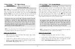
Chart Orientation

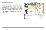
All the chart views allow you to choose the orientation of the chart. When
North-Up orientation is selected, True North is shown at the top of the
display. In other words, objects located to the north of the boat are drawn
above the boat. When Course-Up orientation is selected, the direction of
motion of the boat is shown at the top of the display. In other words, objects
ahead of the boat are drawn above the boat. In both orientations, the view
pans automatically, so that the boat is always centered on the display. When
the boat is stationary, it is drawn as a circle. When the boat is in motion, it
takes on a boat shape, pointed in the direction of motion (always Up in the
Course-Up orientation). See

Navigation Menu Tab: Chart Orientation

for

more information.

Viewing Cartography

In the

Chart

or

Combo

Views, there are several cartography-related

functions that you can access using various keys.

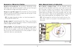
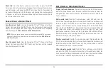
Panning:

Use the 4-WAY Cursor keys to move the chart around on the

display in the direction of the key being pressed. When you do this, a
Bullseye Cursor is drawn at the top of the screen and is linked to the boat by
a yellow line, even if the boat is off the screen. At the same time, a cursor
dialog box is displayed at the top of the screen with the distance and bearing
from the boat to the cursor position and the latitude/longitude coordinates
of the cursor. When the cursor is active on the display, you can also use the
4-WAY Cursor Control key to move the cursor diagonally.

Zooming:

Use the Plus (+) key to Zoom In and the Minus (-) key to Zoom Out

showing the cartography at different scales. The scale is indicated on the left
side of the display. If you zoom in beyond the available chart data, the
display will go into Overzoom mode whereby the last available chart data is
amplified to reflect the scale selected. If you zoom in so far that no
cartography is available, a lat/lon grid will be drawn instead.

Chart Info:

Use the INFO key to get detailed information about the chart. If

the cursor is active, you will see information about the chart objects located
near the cursor. If the cursor is not active, the Chart Info menu will appear.
You can select the nearest port, the nearest tide station, or the nearest
current station to see information about any of these objects.

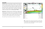
Chart View with Cursor Present

52

Содержание 917C

Страница 1: ......

Страница 2: ...ving water depth may change too quickly to allow time for you to react Always operate the boat at very slow speeds if you suspect shallow water or submerged objects WARNING Disassembly and repair of t...

Страница 3: ...nstallation 21 Trolling Motor Transducer Installation 24 Trolling Motor Transducer Options 25 GPS Receiver Installation 25 Stem Mounting with an Existing 1 14 Thread Stem 26 Access Under Mounting Loca...

Страница 4: ...ing Grid 56 Save Edit or Delete a Route 57 Save or Clear a Current Track 58 Edit Delete or Hide Saved Tracks 58 Man Overboard MOB Navigation 59 The Menu System 60 Start Up Options Menu 61 Normal Opera...

Страница 5: ...MMC SD Card Snapshot and Recording View only 76 Delete All Images optional purchase MMC SD Card Snapshot and Recording View only 76 Delete Recording optional purchase MMC SD Card Snapshot and Recordi...

Страница 6: ...undings 95 Navaids on Bird s Eye View 95 Shaded Depth 95 Set Simulation Position Advanced 96 Set Map Offset Advanced 96 Clear Map Offset Advanced 97 Alarms Menu Tab 97 Depth Alarm 98 Fish ID Alarm 98...

Страница 7: ...117 Returning Your Unit For Service 118 900 Series Accessories 119 Specifications 121 Glossary 122 Contact Humminbird 133 NOTE Entries in this Table of Contents which list International only are only...

Страница 8: ......

Страница 9: ...ve signal and determines distance by measuring the time between the transmission of the sound wave and when the sound wave is reflected off of an object it then uses the reflected signal to interpret...

Страница 10: ...increased power output are the ability to detect smaller targets at greater distances ability to overcome noise better high speed performance and enhanced depth capability DualBeam PLUS Sonar Your 90...

Страница 11: ...Sonar 2 features new temperature sensing and the performance of DualBeam PLUS technology An expanded view and greater bottom detail gives you a totally new perspective of the water below along with op...

Страница 12: ...apabilities with advanced fishfinding The following GPS functionality is currently supported by the 900 Series Fishing System when it is connected to the included GPS receiver View current position Vi...

Страница 13: ...r control head is currently running and will ask you if you want to update the software in the unit to match that on the MMC SD card You can obtain software updates from the www humminbird com website...

Страница 14: ...motor mounting method Installing the GPS Receiver if included Testing the complete installation and locking the transducer position NOTE Accessories may require a separate purchase You can visit our w...

Страница 15: ...nting bracket to the top of the control head will allow for overhead mounting The chosen mounting area should allow for sufficient room so the control head can pivot through the full tilt range and al...

Страница 16: ...nsducer GPS Receiver and accessories Make the required installations and then run the cables to your control head mounting location Do not cut any cabling except the power cable If your cables are too...

Страница 17: ...over and insert the 8 Phillips countersink wood screws Hand tighten only 7 Place the mounting bracket on the mounting surface aligned with the drilled holes and fill the mounting holes with marine gra...

Страница 18: ...lots If you don t have a cable for every hole in the insert install the blank plugs to protect the control head from the weather 1 2 Cables Routed Behind Mounting Bracket 3 Gimbal Bracket 1 Grommet 2...

Страница 19: ...ngle and secure by tightening the gimbal knobs NOTE You may wish to dress the cabling with nylon wire ties in order to hold the cables together and create a cleaner assembly The Humminbird 900 Series...

Страница 20: ...ed prior to installation In addition to the hardware supplied with your transducer you will need a powered hand drill and various drill bits various hand tools including a ruler or straightedge a leve...

Страница 21: ...rbulent water Consider the following to find the best location with the least amount of turbulence As the boat moves through the water turbulence is generated by the weight of the boat and the thrust...

Страница 22: ...adjustment NOTE If you cannot find a transom mount location that will work for your high speed application find an In Hull Transducer by contacting our Customer Resource Center at either 1 800 633 14...

Страница 23: ...provided then mount it and make adjustments to its position without locking it in place NOTE You will initially assemble the transducer and the pivot arm by matching the two ratchets to a numbered pos...

Страница 24: ...hat the square teeth on each ratchet face the square teeth on the transducer knuckle and the triangular teeth face outward Hold the ratchets on the transducer knuckle with one hand and fit the pivot a...

Страница 25: ...assembly with the drilled holes in the transom With a 5 16 socket driver mount the assembly to the transom using the two 10 1 long screws provided NOTE Make sure that the mounting screws are snug but...

Страница 26: ...and test and finish the installation in the following procedures 4 Routing the Cable The transducer cable has a low profile connector which must be routed to the point where the control head is mount...

Страница 27: ...with marine grade silicone sealant Place the escutcheon plate over the cable hole and attach with two 8 x 5 8 wood screws 4 Route and secure the cable by attaching the cable clamp to the transom dril...

Страница 28: ...position for your boat First adjust the height in small increment NOTE The deeper the transducer is in the water the more likely that a rooster tail of spray will be generated at high speeds so make s...

Страница 29: ...xy Do not use silicone or any other soft adhesive to install the transducer as this material reduces the sensitivity of the unit Do not use five minute epoxy as it has a tendency to cure before all th...

Страница 30: ...allation first that includes running the boat at various speeds in order to determine the best mounting area before permanently mounting the transducer 1 Plug the transducer into the control head then...

Страница 31: ...able repeat Steps 3 through 6 7 Once you have determined the best mounting location using the above steps mark the position of the transducer 3 Route the cable 1 Once the mounting location is determin...

Страница 32: ...OTE Neither water spilled gasoline nor oil will affect the performance of the transducer Trolling Motor Transducer Installation If you want to install the transducer on a trolling motor use this proce...

Страница 33: ...To optimize performance of the GPS receiver mount it in an area that has full exposure to the sky The effective area of reception is 10 above the horizon Different circumstances determine the mounting...

Страница 34: ...ld not exceed 50 16 m NOTE Remember to caulk or seal screw holes and drilled holes as needed to protect your boat from water damage 2 Screw on the receiver base to the stem first making sure that the...

Страница 35: ...crews Hand tighten only NOTE If the mounting surface is thin and made of a lighter material a backing material may be needed below the mounting surface No Access Under Mounting Location Follow these s...

Страница 36: ...nly Finish Routing the Cable and Check GPS Receiver Operation After installing a GPS receiver you should perform the following procedure to finish routing the GPS cable to the control head and to chec...

Страница 37: ...he System Status Self Test screen will appear NOTE If you wait too long the system will default to whichever menu mode happens to be highlighted and you will have to start again 2 Self Test displays r...

Страница 38: ...ore information Powering Up the Control Head Turn on your 900 Series control head by pressing the POWER key The Title screen is displayed until the 900 Series begins operation Your 900 Series will beg...

Страница 39: ...es traveled 2 7 Distance Distance traveled with Speed accessory or GPS Receiver 3 Average Speed Average speed reading with Speed accessory or GPS Receiver 4 Thermoclines layers of water with different...

Страница 40: ...m Contour The type of bottom can be determined from the return charted on the display A Hard Bottom such as compacted sediment or flat rock appears as a thinner line across the display A Soft Bottom s...

Страница 41: ...ve you flexibility and control over your fishing experience Your control head has the following keys POWER LIGHT key EXIT key VIEW key 4 WAY Cursor Control key MENU key VIEW PRESET keys MARK key GOTO...

Страница 42: ...p Options Menu Press the MENU key during the power up sequence to view the Start Up Options menu X Press Menu Press the MENU key once for the X Press Menu The X Press Menu allows you to access frequen...

Страница 43: ...ys are used to control the speed of playback NOTE Menu choices are implemented and saved immediately no further action is required VIEW PRESET keys The VIEW PRESET keys are used to program your three...

Страница 44: ...if Screen Snapshot is enabled but there is no GPS receiver connected pressing the MARK key will capture the screen image and display an error saying that a GPS position fix is required to create a way...

Страница 45: ...tomize the information displayed in individual readouts on many views including suppressing a particular readout so that nothing is displayed the ability to customize readouts depends on the view and...

Страница 46: ...cursor and cursor dialog box will be displayed on the screen The cursor can be positioned on the display using the 4 WAY Cursor Control key to determine the depth of any sonar return The RTS Window c...

Страница 47: ...Level or magnification is displayed in the upper left corner and can be changed to suit conditions Upper and Lower Zoom Depth Range numbers indicate the depth of the water which is being viewed Freez...

Страница 48: ...the 4 WAY Cursor Control key will freeze the screen in this view and a cursor and cursor dialog box will be displayed on the screen The cursor can be positioned on the display using the 4 WAY Cursor C...

Страница 49: ...icons in this view The selected thumbnail or icon will be highlighted with arrows NOTE The speed of the screen capture or of the recording depends on the type of card you use in general SD cards captu...

Страница 50: ...e your cursor is on the screen and the screen will freeze while the snapshot is being saved to the MMC SD card A status dialog box will appear that shows the progress of the save as a percentage and t...

Страница 51: ...the bottom of the screen shows the progress of the recording as well as how much space is remaining on the MMC SD card NOTE The waypoints that are created by a recording have the same name as the fil...

Страница 52: ...g View only playback speed can also be changed using the Left and Right 4 Way Cursor keys Playback is paused when the sonar cursor is active and resumes playing when the cursor is removed Playback is...

Страница 53: ...nar X Press menu when in Side Beam View the display will represent the same sonar data in one of the following three layouts Default Classic and Slanted Default layout The top portion of the display p...

Страница 54: ...ts the sonar information from the side looking beams reveals bottom contour structure and fish similar to the down looking beam but the area covered is to the left and right of the area shown in the d...

Страница 55: ...o move and turn the eye point so that you can look off to the sides or even behind the boat Pressing the RIGHT or LEFT arrow keys on the 4 WAY Cursor key turns the eye point right or left while pressi...

Страница 56: ...active You can also adjust the size of the left side of a split screen see Sonar X Press Menu Split Position or Navigation X Press Menu Split Position for more information NOTE See Bird s Eye View an...

Страница 57: ...more information A green arrow points to the side that is active You can also adjust the size of the left side of a split screen see Sonar X Press Menu Split Position or Navigation X Press Menu Split...

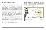
Страница 58: ...aid on the chart You can use the 4 WAY Cursor Control key to shift pan the chart to another area You can use the ZOOM keys to zoom in and out You can use the INFO key to get information on the chart o...

Страница 59: ...more information A green arrow points to the side that is active You can also adjust the size of the left side of a split screen see Sonar X Press Menu Split Position or Navigation X Press Menu Split...

Страница 60: ...rsor is drawn at the top of the screen and is linked to the boat by a yellow line even if the boat is off the screen At the same time a cursor dialog box is displayed at the top of the screen with the...

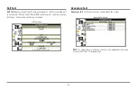
Страница 61: ...to remove the information box and the Bullseye Cursor will be centered over the tide station position The cursor information boxes will indicate the distance and bearing to the tide station from your...

Страница 62: ...h contain up to 50 waypoints Tracks consist of detailed position history and are displayed as a breadcrumb trail of trackpoints The Current Track shows the position history since the unit was powered...

Страница 63: ...reate option and press the RIGHT Cursor key Use the Cursor keys to program a waypoint name latitude longitude and icon before selecting Save Edit a waypoint From the Waypoints submenu select Edit and...

Страница 64: ...nd press the RIGHT Cursor key Canceling navigation removes the route and any waypoints created using the GOTO key but does not remove any saved routes from memory You will be prompted to save the curr...

Страница 65: ...m any view press the MENU key twice to display the Main Menu System then use the RIGHT Cursor key to select the Navigation tab Select Routes and press the RIGHT Cursor key to display the Routes submen...

Страница 66: ...to display the Main Menu System then use the RIGHT Cursor key to select the Navigation tab Select Tracks and press the RIGHT Cursor key to display the Tracks submenu Edit a saved track From the Track...

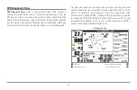
Страница 67: ...nd an additional info box that shows the lat lon position of the MOB waypoint and the elapsed time since MOB was activated is added to the Chart View It is not possible to re activate MOB or modify th...

Страница 68: ...Views and Accessories Press the MENU key twice for the Main Menu then use the 4 WAY Cursor LEFT or RIGHT key to select a tab and use the DOWN or UP key to select a specific menu item under that tab t...

Страница 69: ...is displayed to access the Start Up Options menu Use the UP or DOWN 4 WAY Cursor keys to position the cursor then the RIGHT Cursor key to select one of the following choices If you wait too long the s...

Страница 70: ...y actually do when in Normal operation NOTE To get the full benefit of the Simulator it is important to select Simulator manually from the Start Up Options menu as opposed to letting the 900 Series en...

Страница 71: ...Board PCB serial number software revision total hours of operation and the input voltage Accessory Test Accessory Test lists the accessories connected to the system NOTE The speed accessory will be d...

Страница 72: ...ng monitored but is not yet being used This view also reports the current position local time and date and other numeric information The current GPS Fix Type is reported as No Fix 2D Fix 3D Fix or Enh...

Страница 73: ...s you to select which side of a Combo View will be active key presses will only affect the active side of the screen When a menu is displayed the non active side of the screen will be grayed out at an...

Страница 74: ...30 40 50 60 70 Right Default varies Sensitivity Sensitivity controls how much detail is shown on the display Increasing the sensitivity shows more sonar returns from small baitfish and suspended debr...

Страница 75: ...together to view a specific depth range manually when looking for fish or bottom structure will be displayed in the lower right corner of the screen when you start manually adjusting the Lower Range...

Страница 76: ...e Sonar X Press Menu 2 Use the LEFT or RIGHT 4 WAY Cursor Control keys to increase or decrease the Chart Speed setting 1 10 where 1 Slowest 10 Fastest Default 5 Quad Layout with optional purchase Quad...

Страница 77: ...the LEFT or RIGHT 4 WAY Cursor Control keys to change the Bottom Lock setting to on Off On Default Off 3 Once you turn on Bottom Lock the Bottom Range X Press menu choice will be displayed 10 60 feet...

Страница 78: ...n the left with charts or Bird s Eye usually on the right The Active Side menu choice is only available when a Combo View is active To select the Active Side 1 Highlight Active Side on the Navigation...

Страница 79: ...int in the Chart and Combo Views Delete allows you to delete a waypoint from the list of saved waypoints Target allows you to apply a target to a waypoint selected from the list of waypoints Grid allo...

Страница 80: ...o cancel clearing the current track press the LEFT Cursor key Save Current Route Only when navigating Save Current Route allows you to save the current route being displayed This menu choice will only...

Страница 81: ...de To Cancel MOB Navigation 1 Highlight Cancel MOB Navigation on the Navigation X Press menu 2 Use the RIGHT 4 WAY Cursor Control key to initiate canceling MOB navigation 3 The Confirm dialog box will...

Страница 82: ...Cursor Control key to view the Waypoints submenu The Waypoint Submenu contains the following menu choices Edit allows you to edit the Name Position Latitude and Longitude and select the Icon that will...

Страница 83: ...from the Snapshot and Recording View This menu option is only available when you have an optional purchase MMC SD card installed and you are in Snapshot and Recording View To start sonar recording 1...

Страница 84: ...Press menu 3 Press the RIGHT 4 Way Cursor key to initiate this procedure 4 A Confirm Dialog box will appear Select Yes to delete the image or No to cancel the operation Delete All Images optional pur...

Страница 85: ...IGHT 4 Way Cursor key to initiate this procedure 4 A Confirm Dialog box will appear Select Yes to delete the recording or No to cancel the operation Delete All Recordings optional purchase MMC SD Card...

Страница 86: ...ify the playback speed for a sonar recording from the Snapshot and Recording View This menu option is only available when you have an optional purchase MMC SD card installed and you are playing back a...

Страница 87: ...of time memory left to play is indicated by the status bar For more information see Snapshot and Recording View Sonar Menu Tab Press the MENU key twice to access the Main Menu System and then press t...

Страница 88: ...o select either the 200 kHz beam the 83 kHz beam or the 200 83 kHz beam 200 83 kHz 200 kHz 83 kHz Default 200 kHz Fish ID Fish ID uses advanced signal processing to interpret sonar returns and will di...

Страница 89: ...fying smaller fish species or baitfish Selecting a lower setting displays fewer fish from weak sonar returns This is helpful when seeking larger species of fish Fish Sensitivity is used in conjunction...

Страница 90: ...esents weak returns in blue and strong returns in red WhiteLine highlights the strongest sonar returns in white resulting in a distinctive outline This has the benefit of clearly defining the bottom o...

Страница 91: ...uadraBeam PLUS transducer must be attached to the Fishing System The 455 kHz Sensitivity menu choice is available when Transducer Select is set to QuadraBeam see Sonar Menu Tab Transducer Select and U...

Страница 92: ...or RIGHT 4 WAY Cursor Control keys to turn the Depth Lines setting On or Off Off On Default On Surface Clutter Advanced Surface Clutter adjusts the filter that removes surface clutter noise caused by...

Страница 93: ...Low Max Depth Advanced Max Depth adjusts the maximum depth of operation The performance of your 900 Series can be tuned to the maximum depth you will be fishing in by setting the Max Depth When a max...

Страница 94: ...Salt Default Fresh Transducer Select Transducer Select allows you to select which transducer you want to use NOTE The transducer setting must correspond to the transducer type connected to your system...

Страница 95: ...the display of the Temperature Graph 1 In the Sonar View highlight Temperature Graph on the Sonar main menu 2 Use the LEFT or RIGHT 4 WAY Cursor Control keys to change the display of water temperatur...

Страница 96: ...rack a color range will represent the different depths on the track instead from light green shallowest to black deepest You can change the depth range associated with black by using Track Color Range...

Страница 97: ...atitude and Longitude and select the Icon that will be used to represent the waypoint in the Chart and Combo Views Delete allows you to delete a waypoint from the list of saved waypoints Cursor To all...

Страница 98: ...ch waypoint to the next Chart Orientation Chart Orientation allows you to select whether the views containing charts should be drawn North Up or Course Up To change the Chart Orientation setting 1 Hig...

Страница 99: ...Interval on the Navigation main menu 2 Use the LEFT or RIGHT 4 WAY Cursor Control keys to change the Trackpoint Interval setting 1 second 5 seconds 10 seconds 15 seconds 30 seconds or 60 seconds Defa...

Страница 100: ...hlight Map Datum on the Navigation main menu 2 Use the LEFT or RIGHT 4 WAY Cursor Control keys to change the Map Datum setting Default WGS 84 Course Projection Line Course Projection Line allows you t...

Страница 101: ...n Mode allows you to continue to navigate and fish around a particular waypoint even if you pass over it multiple times To activate or de activate Continuous Navigation 1 Highlight Continuous Navigati...

Страница 102: ...n To change the Chart Detail Level setting 1 Highlight Chart Detail Level on the Navigation main menu 2 Use the LEFT or RIGHT 4 WAY Cursor Control keys to change the Chart Detail Level setting Basic N...

Страница 103: ...ings setting Hidden Visible Default Hidden Navaids on Bird s Eye View Navaids on Bird s Eye View allows you to display or hide additional navigational aids such as lights and buoys in Bird s Eye View...

Страница 104: ...age Exit the menu set the cursor then try again Set Map Offset Advanced Set Map Offset allows you to change the map offset used by the 900 Series NOTE The Map Offset will be applied to all maps and no...

Страница 105: ...ap Offset on the Navigation main menu 2 Use the RIGHT 4 WAY Cursor Control key to clear the Map Offset Alarms Menu Tab From any view press the MENU key twice to access the Main Menu System The Alarms...

Страница 106: ...m Low Battery Alarm sounds when the input battery voltage is equal to or less than the menu setting The battery alarm will only sound for the battery that is connected to the 900 Series The Low Batter...

Страница 107: ...Temp Alarm on the Alarms main menu 2 Use the LEFT or RIGHT 4 Way Cursor Control keys to change the Aux Temp Alarm setting Off 33 120 Fahrenheit 0 50 Celsius Default Off Temp Alarm Temp Alarm sounds w...

Страница 108: ...al models only Default 300 ft 100 m Arrival Alarm Arrival Alarm sounds when the boat has either exceeded the distance to the destination waypoint or has entered the Arrival Alarm Circle based on the m...

Страница 109: ...Alarms main menu 2 Use the LEFT or RIGHT 4 WAY Cursor Control keys to change the Drift Alarm setting Off 25 to 3000 feet 10 to 1000 meters International models only Default Off Alarm Tone Alarm Tone s...

Страница 110: ...nge the Units Depth setting 1 Highlight Units Depth on the Setup menu 2 Use the LEFT or RIGHT 4 WAY Cursor Control keys to change the Units Depth setting Meters International models only Feet Fathoms...

Страница 111: ...nu 2 Use the LEFT or RIGHT 4 WAY Cursor Control keys to change the Units Speed setting kph International models only mph kts Default kph for International models and mph for Domestic models User Mode...

Страница 112: ...rsor key once more To cancel Restore Defaults press the LEFT Cursor key Select Readouts Advanced Select Readouts allows you to customize the information displayed in individual digital readouts on the...

Страница 113: ...View there are two columns of four boxes The first column shows Depth Time To Go TTG Position Lat Lon and Speed The second column shows Cross Track Error XTE Heading Bearing and Distance To Go DTG All...

Страница 114: ...are in Advanced User Mode then highlight Depth Offset on the Setup menu 2 Use the LEFT or RIGHT 4 WAY Cursor Control keys to change the Depth Offset setting 10 0 to 10 0 feet or 3 to 3 meters Interna...

Страница 115: ...or RIGHT 4 WAY Cursor Control keys to change the Local Time Zone Default EST UTC 5 Eastern Standard Time Daylight Saving Time Advanced Daylight Saving Time adjusts the time display to account for loca...

Страница 116: ...e the LEFT or RIGHT 4 WAY Cursor Control keys to change the Time Format 12 hour 24 hour Default 12 hour Date Format Advanced International only Date Format changes the date format used by the unit Thi...

Страница 117: ...utput Advanced NMEA Output turns the NMEA output on or off This menu choice is available only when in Advanced User Mode see Setup Menu Tab User Mode The following NMEA sentences are output DPT Depth...

Страница 118: ...fault On Views Menu Tab From any view press the MENU key twice to access the tabbed Main Menu System then press the RIGHT 4 WAY Cursor Control key until the Views tab is selected This menu tab allows...

Страница 119: ...GHT 4 WAY Cursor Control keys to change the status of the view from Hidden to Visible or vice versa Bird s Eye View Chart Bird s Eye Combo View Chart Chart Combo View Chart View Chart Sonar Combo View...

Страница 120: ...tomatically Once you have created a screen capture a screen capture thumbnail is added to the Snapshot and Recording View and is available to view at a later date See the full sized image by highlight...

Страница 121: ...o To view screen snapshots 1 Make sure that the optional purchase MMC SD card used to capture the screen is installed in your card slot 2 Press the VIEW key until you see the Snapshot and Recording Vi...

Страница 122: ...orrosion from the battery terminals or wiring or actually replacing the battery if necessary 900 Series Defaults to Simulator with a Transducer Attached A connected and functioning transducer will cau...

Страница 123: ...x of air and water flowing around the transducer cavitation may be interfering with the interpretation of sonar data See your Installation Guide for suggestions on adjusting the transducer position El...

Страница 124: ...ears To determine whether the boat s engine is the source of the noise increase the RPMs while the boat is in neutral and stationary to see if the noise increases proportionately if noise appears when...

Страница 125: ...T FOR ANY APPLICABLE IMPLIED WARRANTIES UNDER STATE LAW WHICH ARE HEREBY LIMITED IN DURATION TO ONE YEAR FROM THE DATE OF ORIGINAL PURCHASE IN NO EVENT WILL HUMMINBIRD BE LIABLE FOR ANY INCIDENTAL OR...

Страница 126: ...nclude your Repair Authorization Number in all subsequent communications about your unit For IN WARRANTY service complete the following steps Obtain a Repair Authorization Number from the Humminbird C...

Страница 127: ...Electronics Association standard for data communication Wireless Sonar Link WSL purchase the Wireless Sonar Link WSL accessory to receive remote sonar signals from a SmartCast Remote Sonar Sensor RSS...

Страница 128: ...he fish With the new InterLink Network Connection you can now share GPS position waypoints routes and your current track between two Humminbird Fishing Systems in real time Mark a waypoint at the cons...

Страница 129: ...entally responsible disposal during the product life cycle WEEE compliance may not be required in your location for electrical electronic equipment EEE nor may it be required for EEE designed and inte...

Страница 130: ...ker and less black It is important to note that a sonar return from a sloping bottom can have the appearance of a softer bottom Cavitation Cavitation is the effect of air bubbles created as the propel...

Страница 131: ...Frame is a Humminbird feature that pauses the sonar scrolling so that the image on screen can be studied with greater detail See Instant Image Update Frequency Frequency is a measure of the number of...

Страница 132: ...horizontal number i e 640 V x 320 H this key specification typically indicates the quality of resolution In fishfinders the total resolution vertical multiplied by horizontal is often less important...

Страница 133: ...rgy bouncing off the bottom once rebounding to the water surface and then traveling back down to the bottom to be reflected again Second returns are more common in shallow water and over hard bottoms...

Страница 134: ...flected off of tiny objects near the surface of the water including algae and even air bubbles Typically saltwater environments have significantly greater surface clutter than freshwater due to contin...

Страница 135: ...the strong signal overwhelming the weak signal See Transducer and Noise TripLog TripLog is a Humminbird feature that provides an on screen counter for Elapsed Time Average Speed and Total Distance tra...

Страница 136: ...osition from at least three satellites Humminbird GPS receivers provide very fast acquisition times under one minute permitting users to get out on the water faster Alarm Arrival The audible alert tha...

Страница 137: ...To Go See Time to Go and Speed Over Ground Estimated Position Error EPE Estimated Position Error is a calculation that indicates the potential position inaccuracy the user may experience due to a var...

Страница 138: ...mpass uses Magnetic North Humminbird GPS units provide the option of selecting True or Magnetic readouts by using the North Reference menu See Magnetic North Present Position Present Position is the c...

Страница 139: ...ents the most efficient path between the two points because it is a straight line The TRK is measured in degrees i e 321 where 000 is North 090 East 180 is South 270 is West See Cross Track Error and...

Страница 140: ...ability to name and assign a symbol to the saved location Depth Date and Time of Day when the waypoint was created is also saved Waypoint Target Waypoint Target is a Humminbird feature that displays...

Страница 141: ...By Telephone Monday Friday 8 00 a m to 4 30 p m Central Standard Time 1 800 633 1468 By e mail typically we respond to your e mail within three business days cservice johnsonoutdoors com For direct sh...

Отзывы: