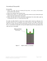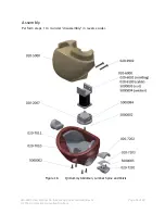
020-9905 User Manual Q3 (Advanced 3 year old child) Rev G Page 34 of 82
© 2016 Humanetics Innovative Solutions
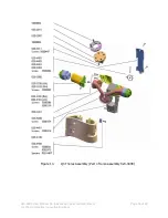
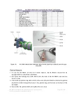
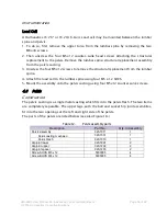
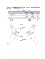
Table 9.
IR-TRACC attachment: part list frontal impact configuration
Description
Part No.
Qty. in Assembly
Pivot Pin - Gimbal
020-4402
2
Gimbal Shaft
020-4403
1
E-clip
5000751
2
Shaft Locking Boss
020-4404
1
Gimbal Ring
020-4405
1
Screw SSCP M5 x 5
5000406
1
Attachment IR-TRACC
020-4406
1
Spacer IR-TRACC Attachment
020-4407
2
Screw SHCS #5-40 x 5/8
9002975
1
Screw FHCS M4 x 0.7 x 10
5000023
2
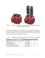
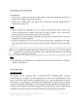
Figure 15.
IR-TRACC attachment hardware spine frontal (right top & bottom) and rib cage
side (left)
Frontal Impacts
1.
To use the IR-TRACC (IF-362) for frontal impacts, the IR-TRACC should first be
equipped with its attachment hardware.
2.
First place the holding boss (020-4404) onto the back of the IR-TRACC and unscrew
the set screw.
3.
Then hold the gimbal ring (020-4405) at the end of the IR-TRACC and slide the gimbal
shaft (020-4403) through the holes in the gimbal ring and the hole in the back of the
IR-TRACC.
4.
Now centre the gimbal shaft and tighten the set screw.
020-
4402

