020-9905 User Manual Q3 (Advanced 3 year old child) Rev G Page 14 of 82
© 2016 Humanetics Innovative Solutions
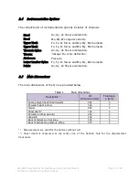
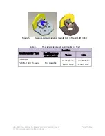
Lumbar Spine
Standard - 6 channel load cell at lumbar spine/ pelvis interface (Fx, Fy, Fz, Mx, My,
Mz). Humanetics Model IF-217 (350 Ohm) or IF-218 (120 Ohm).
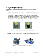
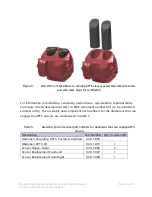
Abdomen
Optional - Abdomen Pressure Twin Sensors (APTS)
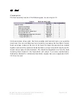
Pelvis
Standard - 3 uni-axial accelerometers (or tri-axial accelerometer) on pelvis skeletal
structure (Ax, Ay, Az).
Notes:
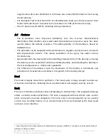
1. IR-TRACC sensor may be mounted in two ways, either to measure frontal or lateral
deformations. The IR-TRACC sensor cannot record the true deformation in oblique
impacts. It is recommended not be use the IR-TRACC in tests with expected high oblique
rib deformations; this can cause damage to the IR-TRACC sensor, as it has limited range
of motion in directions perpendicular to its sensitive deflection direction.
2. Information on the installation of the instrumentation can be found in the
assembly/disassembly section of this manual.
3. The Upper Neck Load Cell does not require any correction for measurement of the
moment around the OC joint. The (theoretical) OC joint coincides with the neutral axis of
the moment measurement of the (Humanetics) load cell.
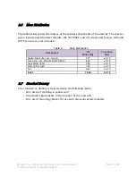
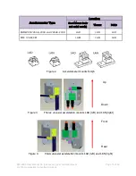
4. Additional accelerometers may be mounted in the dummy for extra/redundant
information. There are no fixed points for attaching these accelerometers. Instead,
double-sided tape may be used to attach the accelerometer to the desired location. Two
accelerometers may be used to measure deformation velocity and the deformation itself.
The procedure is as follows:
Install the accelerometers in the dummy. The sensitive axes of the transducers should be
aligned as good as possible. Furthermore, the accelerometers should be installed in
locations that are expected to retain their alignment during the deformation phase. Make
sure that the accelerometers are not located on positions that may contact other parts of
the dummy as a result of deformation. To process and combine the data first filter both
signals at CFC1000 according to SAE J211. Subtract the signals and integrate the result.
This results in the deformation velocity. Numerical integration of this signal gives the
deformation itself.


