


020-9905 User Manual Q3 (Advanced 3 year old child) Rev G Page 42 of 82
© 2016 Humanetics Innovative Solutions
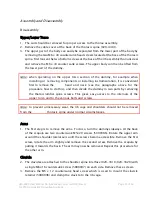
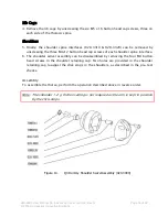
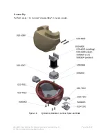
Assembly and Disassembly
Disassembly
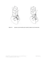
It is not advised to disassemble the legs, except to replace broken parts. To separate the
lower from the upper leg:
1.
Remove the motion stop screw (020-9901) located on the inside of the knee joint.
2.
Remove the M8x30 socket head shoulder screw (020-9908) connecting the two parts
of the leg.
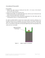
Assembly
1.
Check that the rubber end stops are in the correct position inside the upper knee joint
before assembly of the lower leg.
2.
Align upper and lower leg at shoulder screw holes and screw in shoulder screw.
3.
Before inserting the motion stop screw, place upper and lower leg in a 90º angle with
respect to each other.
4.
Turn the motion stop screw into the leg as far as it will go. Then turn it back half a
turn and check that the motion of the lower leg is without significant friction.
Note:
It is not possible to change the friction setting of the knee joint in the legs. The
legs are fully supported and positioned by the child restraint system.
Instrumentation
No instrumentation is used in the legs.
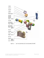
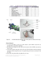
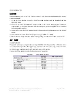
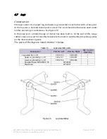
4.8 Arms
Construction
The arms consist of an upper and lower section, connected at the elbow with a joint. At
the upper end, a shoulder joint allows a number of degrees of freedom. The main joint is
of the ball-and socket type, with a limited range of motion. The upper arm can rotate
around its vertical axis. Furthermore, the entire arm can rotate around the shoulder lateral
axis. See figure 21.