Installation Manual – Antenna & Feeder System Installation
BTS3802C & RRU
Chapter 2
Installing RF Antenna & Feeder System
2-32
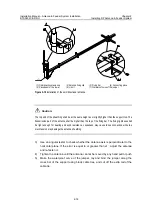
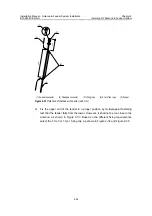
clockwise 120° direction, as shown in Figure 2-21. By turning the antenna slightly,
the personnel can adjust the azimuth angle until it satisfies the design index.
Usually, the error of the azimuth angel shall be
[
5°.
4) Tighten up the lower fixing clip of the antenna until it cannot be moved by any
hand pull or push.
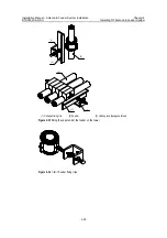
5) Adjust the pitch angle of the antenna. If the mounting hole of each directional
antenna has its corresponding pitch angle, the antenna can be installed directly
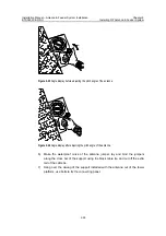
into the mounting hole as shown in Figure 2-22 and Figure 2-23. However, the
supporting post shall be kept perpendicular to the ground during the installation.
For other antennas, please refer to “2.10.5 Adjust the Pitch Angles” for the
procedure of adjusting pitch angles
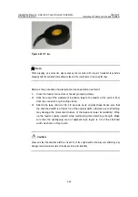
6) Make the waterproof curve of the antenna jumper, lay and bind the jumpers
along the cross bar of the support using the black cable tie, and cut off the extra
tail of the cable tie.
Caution:
z
Take care to protect the installed jumpers from damage during the course of installing and adjusting
the antenna.
z
When using the compass, keep it away from the tower and other iron and steel objects. Be careful of
any geomagnetic abnormality that can interfere in the accurate operation of the compass.
z
The jumpers shall bend in a natural manner. The bending radius shall be 20 times longer than the
jumper diameter.
z
The cable ties shall be wound in the same way. For the cuttings, there shall be a slack of 5~10 mm
left lest the tape falls off the jumper due to temperature changes.
2.10.5 Adjust the Pitch Angles
The procedures of adjusting the pitch angles show below:
1) Decide the pitch angle of the antenna using the angle display, as shown in
Figure 2-24 and Figure 2-25.
2) By turning the antenna slightly, adjust the pitch angle until it satisfies the
engineering design index, as shown in Figure 2-26. Usually, the error of the pitch
angle is required to be
[
0.5°.
3) Tighten up the upper fixing clip of the antenna until it cannot be moved by any
hand pull or push.

