background image

I. General conventions 

Convention Description 

Arial 

Normal paragraphs are in 

Arial

Arial Narrow


Warnings, Cautions, Notes and Tips are in Arial Narrow. 

Boldface 

Headings are in 

Boldface

.  


II. Symbols 

Eye-catching symbols are also used in the manual to highlight the points worthy of 
special attention during the operation. They are defined as follows: 


Caution

,

 Warning

Danger

: Means reader be extremely careful during the 

operation. 


Note

: Means a complementary description. 

Environmental Protection


This product has been designed to comply with the requirements on 
environmental protection. For the proper storage, use and disposal of this product, 
national laws and regulations must be observed.


Содержание RRU

Страница 1: ... 2 4 2 Installation Requirements 2 5 2 4 3 Installation Flow 2 6 2 5 Installing Antenna Support on Roof 2 8 2 5 1 Structure of the Antenna Support 2 8 2 5 2 Installation Requirements 2 9 2 5 3 Installation Flow 2 10 2 5 4 Installing the antenna support on the roof without wall 2 11 2 5 5 Installing the antenna support onto the roof with wall 2 12 2 6 Hoisting Antennas 2 14 2 6 1 Appearances of Ant...

Страница 2: ...e of Feeder Grounding Clips 2 37 2 13 4 Grounding position 2 39 2 14 Installing Feeder Window 2 41 2 14 1 Structure 2 41 2 14 2 Installation Procedure 2 42 2 15 Leading Feeders into Equipment Room 2 43 2 15 1 Principles of Arrangement 2 43 2 15 2 Installation Procedures 2 43 2 16 Installing Jumpers 2 44 2 16 1 Installation Requirements for Jumpers 2 44 2 16 2 Installing Jumpers 2 44 2 17 Testing A...

Страница 3: ...cking Antenna Feeder System of Mini NodeB 4 1 4 3 Checking Antenna Feeder System of GPS 4 4 Appendix A Interval Requirements for Antenna Installation A 1 A 1 About This Appendix A 1 A 2 Interval Requirements for Omnidirectional Antenna A 1 A 3 Interval Requirements for Directional Antenna A 1 A 4 Interval Requirements for NodeB Co Located with GSM CDMA BTS A 2 A 4 1 Interval Requirements for NodeB...

Страница 4: ...HUAWEI BTS3802C RRU Installation Manual Antenna Feeder System Installation V100R003 ...

Страница 5: ...i Technologies Co Ltd provides customers with comprehensive technical support and service Please feel free to contact our local office or company headquarters Huawei Technologies Co Ltd Address Administration Building Huawei Technologies Co Ltd Bantian Longgang District Shenzhen P R China Postal Code 518129 Website http www huawei com Email support huawei com ...

Страница 6: ...Tellwin Inmedia VRP DOPRA iTELLIN HUAWEI OptiX C C08 iNET NETENGINE OptiX iSite U SYS iMUSE OpenEye Lansway SmartAX infoX TopEng are trademarks of Huawei Technologies Co Ltd All other trademarks mentioned in this manual are the property of their respective holders Notice The information in this manual is subject to change without notice Every effort has been made in the preparation of this manual ...

Страница 7: ...Initial field trial release T2 030405 20040731 C 1 31 Second field trial release T2 030405 20041001 C 1 32 Third field trial release Updates of Contents Updates between manual versions are cumulative Therefore the latest manual version contains all updates made to previous versions Updates Made between Versions 1 31 and 1 30 1 Adding the antenna feeder installation of RRU 2 Changing the Figure 2 1...

Страница 8: ...Chapter 3 Installing GPS Antenna Feeder System describes the installation methods and procedures of the GPS antenna feeder system of BTS3802C Chapter 4 Installation Checking lists the checking items and requirements for the RF antenna and feeder system and GPS antenna and feeder system Appendix A Interval Requirement for Antenna installation introduces the interval requirements for directional ant...

Страница 9: ...ual to highlight the points worthy of special attention during the operation They are defined as follows Caution Warning Danger Means reader be extremely careful during the operation Note Means a complementary description Environmental Protection This product has been designed to comply with the requirements on environmental protection For the proper storage use and disposal of this product nation...

Страница 10: ...Antenna Support on Tower 2 4 2 4 1 Structure of Antenna Support 2 4 2 4 2 Installation Requirements 2 5 2 4 3 Installation Flow 2 6 2 5 Installing Antenna Support on Roof 2 8 2 5 1 Structure of the Antenna Support 2 8 2 5 2 Installation Requirements 2 9 2 5 3 Installation Flow 2 10 2 5 4 Installing the antenna support on the roof without wall 2 11 2 5 5 Installing the antenna support onto the roof...

Страница 11: ...quence 2 37 2 13 3 Installation Procedure of Feeder Grounding Clips 2 37 2 13 4 Grounding position 2 39 2 14 Installing Feeder Window 2 41 2 14 1 Structure 2 41 2 14 2 Installation Procedure 2 42 2 15 Leading Feeders into Equipment Room 2 43 2 15 1 Principles of Arrangement 2 43 2 15 2 Installation Procedures 2 43 2 16 Installing Jumpers 2 44 2 16 1 Installation Requirements for Jumpers 2 44 2 16 ...

Страница 12: ...This Chapter 4 1 4 2 Checking Antenna Feeder System of Mini NodeB 4 1 4 3 Checking Antenna Feeder System of GPS 4 4 Appendix A Interval Requirements for Antenna Installation A 1 A 1 About This Appendix A 1 A 2 Interval Requirements for Omnidirectional Antenna A 1 A 3 Interval Requirements for Directional Antenna A 1 A 4 Interval Requirements for NodeB Co Located with GSM CDMA BTS A 2 A 4 1 Interva...

Страница 13: ...unding bar 1 2 3 Figure 2 3 Installation of indoor grounding bar 2 2 3 Figure 2 4 Structure of the antenna support on tower unit mm 2 5 Figure 2 5 Installation of the lightning rod 2 6 Figure 2 6 Installation flow of antenna support on the tower 2 7 Figure 2 7 Installing the antenna support on the tower platform 2 7 Figure 2 8 Structure of the antenna support on the roof 2 9 Figure 2 9 Procedure o...

Страница 14: ...ting the pitch angle of the antenna 2 25 Figure 2 27 Installing the omnidirectional antenna onto the support at the roof 2 27 Figure 2 28 Procedure of installing the omnidirectional antenna on the roof 2 28 Figure 2 29 Installing the directional antenna at the roof without wall 2 30 Figure 2 30 Installing the directional antenna at the roof with wall no shorter than 1200mm 2 31 Figure 2 31 Procedu...

Страница 15: ...m 3 2 Figure 3 2 Installing antenna 3 3 Figure 3 3 Structure of the antenna stand on the tower 3 4 Figure 3 4 Installed antenna support on tower 3 5 Figure 3 5 Structure of GPS antenna support 3 6 Figure 3 6 GPS antenna of Type UNONCORE 3 8 Figure 3 7 Appearance of Type iS MR50LNZ 6 lightning arrester 3 9 Figure 3 8 Appearance of Type DGXZ 6NFNM A lightning arrester 3 10 Figure 3 9 Installation pr...

Страница 16: ... vii List of Tables Table 1 1 List of tools instruments exclusively for antenna and feeder system installation1 2 Table 4 1 Check items of the antenna feeder system of mini NodeB 4 1 Table 4 2 Check items of the antenna feeder system of GPS 4 4 Table B 1 Contents of feeder label B 2 ...

Страница 17: ...hapter This chapter describes the installation preparations of antenna and feeder system including z Personnel Requirements z Preparation Tasks for Different Installation Roles z Tools Instruments Preparation z Testing Antenna Feeder Equipment z Adding Feeder Connector z Assembling Antenna 1 2 Personnel Requirements The antenna feeder system is installed by the antenna feeder installation personne...

Страница 18: ...ildren away from the engineering site and to take care installation parts and instruments and prevent loss or damage from occurring z The personnel on the tower must fasten safety belts and get the tool kit and some simple bandages such as the Woundplast handy Caution z When multiple persons are to climb the tower the person carrying the tool kit should climb up last and down first lest a barely f...

Страница 19: ...a Feeder Equipment To guarantee the quality of the installation of the antenna feeder system it is suggested that the antenna feeder equipment be tested before the installation To reduce the operations on the tower please test the equipment assemble the antenna and add the feeder connectors on the ground In the case of roof installation if there is enough space the preparation can be done on the r...

Страница 20: ...nt is not powered on If the test result is much different from the corresponding index the TTA should be replaced Note Normally the TTA should be tested when it is powered on for the result is better than that in power off case The test mentioned above simplified is a simplified operation applicable to occasions without corresponding test If conditions permit installer should also test the current...

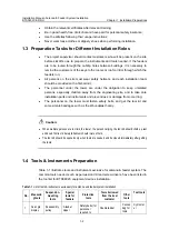
Страница 21: ... onsite since they have all been added before delivery If it is necessary to add them onsite please follow the instructions in their packing boxes Caution If the connector has not been added to the feeder or the connector has been add to the feeder but the feeder has not been connected with the jumper and the remaining operation needs to be done on the next day then apply simple water treatment to...

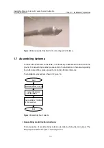
Страница 22: ...ng method please refer to the instruction in the antenna packing box After assembling please keep the instruction for later reference The installation procedure is shown in Figure 1 3 Start Install the antenna fixing clip Apply waterproof treatment to the connectors Connect the antenna with the jumper End Figure 1 3 Assembling flow of antenna I Assembling omnidirectional antenna The accessories of...

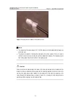
Страница 23: ...ing clips for omnidirectional antenna with different installation methods Figure 1 4 and Figure 1 5 illustrate two of them The actual installations of fixing clips depend on the specific conditions The following description is based on the case adopting the fixing clip shown in Figure 1 4 The procedure of assembling the omnidirectional antenna is as follows 1 Add the two fixing clips onto the omni...

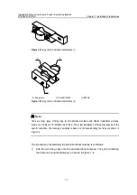
Страница 24: ...erproof treatment to the connectors joining the antenna and the feeder See 2 13 1 Waterproof Treatment for Outdoor Connectors Note Steps 2 and 3 can be performed on the tower When wrapping up a connector please wrap up the connector with a layer of insulation tape before wrapping with the semiconductive adhesive tape for the convenience of removing the tape II Assembling directional antenna The ac...

Страница 25: ...ngle adjuster and the bottom is for fixing the antenna on the support 2 Install the accessories to their proper places in strict accordance with the accessory assembly drawings provided by the supplier 3 Connect the connector of the jumper with that of the antenna and tighten the connection 4 Apply waterproof and encapsulation treatment to the connectors joining the antenna and the feeder See 2 13...

Страница 26: ...apter 1 Installation Preparations 1 10 Figure 1 9 Finished connection of jumpers and directional antenna Caution The spring washers and flat washers should be applied both for the antenna fixing clip and pitch angle adjuster The spring washes should be on the flat washers ...

Страница 27: ...ing and Fixing Feeders z Installing Feeder Window z Leading Feeders into Equipment Room z Installing Jumpers z Testing Antenna Feeder System z Waterproof Treatment for Connectors and Feeder Window 2 2 Procedure of Installing RF Antenna Feeder System This chapter introduces the installation procedure of antenna feeder system of BTS3802C and RRU The installation of antenna feeder system can be imple...

Страница 28: ...oof Refer to 2 5 Hoisting Antennas Refer to 2 10 Cutting Feeders Refer to 2 15 Installing Jumpers Refer to 2 16 Testing Antenna feeder System Waterproof treatment for connectors and feeder window Refer to 2 17 Waterproof Treatment for Connectors and Feeder Window Refer to 2 11 Hoisting and Fixing Feeders Refer to 2 12 Laying and Fixing Feeders Refer to 2 13 Installing Feeder Window Refer to 2 14 L...

Страница 29: ...n install the grounding bar near the feeder window and the optimum installation position is the place right below the feeder window Its installation is shown in Figure 2 2 and Figure 2 3 1 2 3 4 5 6 1 Nut M12 2 Spring washer 12 3 Big plain washer 4 Insulating washer a 5 Insulating washer b 6 Expansion bolt and expansion nut Figure 2 2 Installation of indoor grounding bar 1 1 2 3 4 6 7 5 1 Nut M12 ...

Страница 30: ...s section can be skipped The requirements and the installation methods of the support differ according to the different antenna types and installation environment 2 4 Installing Antenna Support on Tower and 2 5 Installing Antenna Support on Roof only describe the common installation case As for other cases please refer to the engineering documents and the support instructions 2 4 1 Structure of An...

Страница 31: ...pport on tower unit mm 2 4 2 Installation Requirements z The installation plane of the antenna support shall be perpendicular to the level plane z The mast for the tower lightning rod shall be installed separately satisfying the requirements for the lightning protection of all antennas When the antenna support hangs over the tower platform make sure that the antenna on the support is in the effect...

Страница 32: ...a z If possible install hanging devices to strengthen the antenna support and to avoid possible deformation in the future z The dwang shall be reinforced using a stiffener The lengths of expansion link and the dwang shall satisfy the actual need The cross section shall be sealed by soldering with a plate for waterproof purpose z Confirm the reliability of all soldering joints There shall be no dry...

Страница 33: ...g the fixed pulley When the support is going up use another rope to maintain the rising direction of the support 2 Determine the installation position of the antenna support on the tower platform according to the antenna feeder installation drawing in the engineering design drawings 3 Hang over the support out of the tower platform and fix it onto the tower using a U fixing clip including the conn...

Страница 34: ...on of antenna support is usually done by the customer following the requirements designed by the vendor If a support meeting the requirements has already been installed on the site this section can be skipped The requirements and the installation methods of the support differ according to the different antenna types and installation environment 2 4 Installing Antenna Support on Tower and 2 5 Insta...

Страница 35: ...rpendicular to the level plane z For installation of the directional antenna on the roof the antenna support shall be equipped with a lightning rod and be connected with the lightning net of the building z For installation of the omnidirectional antenna on the roof the antenna support generally shall not be installed with a lightning rod Instead the lightning rod shall be installed on a separate s...

Страница 36: ...ll the stiffener Connect the main supporting posts 1 2 Wall 1200 mm tall Y N Fix the two fixing points of the support respectively on the wall and the floor of the roof Connect the base of the support to the lightning net of the building using the connecting bar Soldered parts processing End The support connected to the lightning net of the building N Y Fix the two fixing points of the support on ...

Страница 37: ... the antenna support base 5 Reinforce the main supporting post by using the stiffener The length of the main supporting post decides that of the stiffener As shown in Figure 2 8 connect the stiffener with the main supporting post securely using the connecting pieces of the stiffener Connect the anchor onto the stiffener Fix each anchor of the stiffener onto the surface of the roof using two expans...

Страница 38: ...rate support 2 5 5 Installing the antenna support onto the roof with wall If the roof is enclosed with walls it is not easy to install the antenna support onto the surface of the roof In this case the antenna support can be installed on the wall Figure 2 11 shows how to mount the fixing clip of the antenna support onto the wall 1 2 3 4 5 1 Expansion bolt M12 120 2 V connecting piece 3 180 connecti...

Страница 39: ... 12 Fixing the antenna support onto the wall no shorter than 1200mm When the wall is shorter than 1200mm fix one fixing point of the main supporting post onto the wall using expansion bolts and the other onto the surface of the roof as shown in Figure 2 13 Figure 2 13 Fixing the antenna support onto the wall shorter than 1200mm ...

Страница 40: ...al antenna Figure 2 14 Antennas 2 6 2 Procedure of Hoisting Antennas Figure 2 15 shows how to hoist the directional antenna The hoisting of the other articles can be the same Figure 2 15 Hoisting the directional antenna 1 Mount a fixed pulley at the tower top thrill a rope through the pulley 2 Knot the rope at each end of the antenna 3 The personnel on the tower and on the ground cooperate in hois...

Страница 41: ...e packed in the tool bag and then be hoisted z The hoisted articles shall be put in the place where it is not easy to slip and make some safety treatments 2 7 Installing Omnidirectional Antenna on Tower Platform This section describes the installation method of omnidirectional antenna on tower platform Warn To guarantee the project quality and the safety of constructors the installation shall be c...

Страница 42: ...al antenna onto the tower make sure that the antenna lies in the protection coverage of the lightning rod and that the antenna is at least 2 m away from the tower body z The antenna axis shall be perpendicular to the level plane and the possible error shall be less than 1o z The gain of omnidirectional antenna shall be 10 dBi and the isolation degree shall be 30 dB For details refer to Appendix A ...

Страница 43: ...Adjust and fix the antenna again Tighten up the antenna Figure 2 17 Procedure of installing the omnidirectional antenna 2 7 4 Installation Procedures The installation procedures of installing omnidirectional antenna on tower platform show below 1 Decide the installation location of the antenna according to the engineering design drawings 2 Place the feeding point of the antenna facedown and the sh...

Страница 44: ...f the antenna shall be higher than the top of the fixing bar The fixing tightness shall be right enough for bearing and wind resistance Looseness may cause loose connection while too much tension may damage the antenna sheathing 3 Use an angular tester to check whether the antenna axis is perpendicular to the horizontal plane If the error is equal to or greater than 1ÿ adjust the antenna and re fa...

Страница 45: ...form for the installation personnel This further guarantees the security to the operating personnel fixing the antenna with the feeder After fixing the antenna with the feeder on one side change the location of the wood board on the support arms to fix other antennas with other feeders 2 8 Installing Directional Antennas on Tower Platform This section describes the installation method of direction...

Страница 46: ...otection coverage of the lightning rod No interference from the tower structure shall exist in the forward direction of the antenna The length of the antenna protruding from the tower platform shall be no less than 1 m z The gain of antenna shall be 15 dBi the isolation degree 30 dB and the semi power angle 65 For details on antenna interval refer to the Appendix A Interval Requirement for Antenna...

Страница 47: ...and bind the jumpers End Y Fasten the antenna Adjust the pitch angle Figure 2 20 Procedure of installing the directional antenna 2 8 4 Installation Procedures The installation procedures of installing directional antenna on tower platform show below 1 Decide the installation direction of the antenna according to the project installation drawings 2 Fix the antenna onto the main supporting post The ...

Страница 48: ... the sector 4 Tighten the lower fixing clip of the antenna until it cannot be moved by any hand pull or push 5 Adjust the pitch angle of the antenna If the mounting hole of each directional antenna has its corresponding pitch angle the antenna can be installed directly into the mounting hole as shown in Figure 2 22 and Figure 2 23 However the supporting post shall be kept perpendicular to the grou...

Страница 49: ... number according to the antenna pitch angle Figure 2 22 Diagram 1 for the directional antenna with the mounting hole corresponding to the pitch angle Get the mounting hole according to the mounting hole number Figure 2 23 Diagram 2 for the directional antenna with the mounting hole corresponding to the pitch angle Figure 2 24 Angle display ...

Страница 50: ...ntenna Figure 2 26 Angle display after adjusting the pitch angle of the antenna 6 Make the waterproof curve of the antenna jumper lay and bind the jumpers along the cross bar of the support using the black cable tie and cut off the extra tail of the cable tie 7 Hang over the dwang of the support installed with the antenna out of the tower platform use bolts to fix the connecting panel ...

Страница 51: ...er due to temperature change z The definitions of the main and diversity of the two interfaces of the 2 diversity directional antennas of the same type shall be consistent For example the 45 interface is defined as main interface and the 45 interface is defined as diversity interface 2 9 Installing Omnidirectional Antenna on Roof This section describes the installation method of omnidirectional an...

Страница 52: ...as on the tower platform For details refer to section 2 7 2 Installation Requirements Besides the following points shall also be noted z Keep away from the defilades to avoid the signal blind area when installing antennas z If there is no lightening rod on the top of the antenna support install a lightening rod separately and make sure the distance between omnidirectional antennas and the lighteni...

Страница 53: ...s The installation procedures of installing omnidirectional antenna on roof show below 1 Decide the installation location of the antenna according to the engineering design drawings 2 Place the feeding point of the antenna facedown and the sheathing near the main supporting post of the support then fix the antenna to the fixing bar of the support Caution The top end of the sheathing shall be at th...

Страница 54: ...ng radius shall be 20 times longer than the jumper diameter The cable ties shall be wound in the same way When cutting the cable ties there shall be a slack of 5 10 mm left lest the cable ties fall off the jumper due to temperature change 2 10 Installing Directional Antennas on Roof This section describes the installation method of directional antenna on roof Warn To guarantee the project quality ...

Страница 55: ...eder System Installation BTS3802C RRU Chapter 2 Installing RF Antenna Feeder System 2 29 1 Antenna 2 Cable tie 3 Feeder 4 Stiffener 5 Mat of the supporting post Figure 2 29 Installing the directional antenna at the roof without wall ...

Страница 56: ...ents of the isolation degree and the installation interval of the directional antennas are the same as those for installing the directional antennas on the tower platform For details please refer to section 2 8 2 Installation Requirements Besides the following points shall also be noted z Keep away from the defilades to avoid the signal blind area when installing antennas z The support must be ins...

Страница 57: ...tenna on the roof 2 10 4 Installation Procedures The installation procedures of installing directional antenna on roof show below 1 Decide the installation direction of the antenna according to the project installation drawings 2 Fix the antenna onto the main supporting post The fixing tightness shall be right enough for bearing and wind resistance Looseness may cause loose connection while too mu...

Страница 58: ...f the support using the black cable tie and cut off the extra tail of the cable tie Caution z Take care to protect the installed jumpers from damage during the course of installing and adjusting the antenna z When using the compass keep it away from the tower and other iron and steel objects Be careful of any geomagnetic abnormality that can interfere in the accurate operation of the compass z The...

Страница 59: ...ng each piece Note z For information about feeder label please refer to B 2 Engineering Label of Feeder z The content of the temporary label is the same as that of the formal engineering label Please tear out the temporary labels before binding plastering the formal ones 2 12 Hoisting and Fixing Feeders Caution Be careful during the hoisting No violent hoisting is allowed to avoid damage to the fe...

Страница 60: ...not of the rope 5 Feeder Figure 2 32 Protection of the feeder connector unit mm 3 Fix the upper end of the feeder in a proper position by multiple point fastening lest that the feeder falls from the tower However it shall not be too close to the antenna as shown in Figure 2 33 Based on the different fixing requirements select the 1 for 3 or 1 for 1 fixing clip as shown in Figure 2 34 and Figure 2 ...

Страница 61: ...allation BTS3802C RRU Chapter 2 Installing RF Antenna Feeder System 2 35 1 2 3 2 1 3 1 C shaped fixing clip 2 Feeder 3 Cabling rack hexagonal steel Figure 2 33 Fixing the upper end of the feeder on the tower Figure 2 34 1 for 1 Feeder fixing clips ...

Страница 62: ...d in the same way For the cuttings there shall be a slack of 5 10 mm left lest the tape shall fall off the jumper due to temperature changes 2 13 Laying and Fixing Feeders 2 13 1 Layout Principles z The minimum bending radius of the feeder shall be 20 times longer than the feeder diameter z Feeders shall not cross each other when running along the cabling rack or down the tower The feeders from th...

Страница 63: ...el shall be bound to a feeder using a black tie at the following positions z The point 200 mm away from the lower connector under the outdoor antenna z The point 200 300 mm down the tower platform z The point 200 mm away from the outside of the feeder window z The bent When binding labels to the feeders make sure that they are neatly laid out All labels shall face the same direction and so shall t...

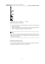
Страница 64: ...driver to force against the grounding cable of the feeder as shown in 4 5 and 6 of Figure 2 36 Caution The grounding cable of the clip shall be led downward and the angle resulting from the grounding cable and the feeder shall be no larger than 150 Make sure the feeder grounding clip bends properly 4 Implement waterproof and encapsulation treatment to the grounding point See 2 18 1 Waterproof Trea...

Страница 65: ...or grounding bar If no outdoor grounding bar is available they can be connected to the well grounded outdoor cabling rack or to the lightning protection grounding net of the building Caution The grounding cable as well as the grounding connector shall go through the antirust treatment The lug nut and cabling racks shall be coated with antirusting paint The bare wire and the lug handle shall be wra...

Страница 66: ...outed down the iron tower platform z 1m around the point where the feeder is routed onto the outdoor cabling rack z Near the outside of feeder window z Near the grounding bar inside the equipment room For mast installation z 1m 2m down the antenna z 1m around the point where the feeder is routed down the mast z The point where the feeder is routed down the roof z Near the outside of feeder window ...

Страница 67: ...e grounding bar inside the equipment room 2 14 Installing Feeder Window 2 14 1 Structure There are two types of feeder windows One is of the 12 hole type and the other of the 27 hole type The 12 hole feeder window is used mostly Figure 2 37 shows the size of it and Figure 2 38 shows the structure of it 400 170 170 400 170 170 Figure 2 37 Size of the 12 hole feeder window unit mm 1 4 3 2 1 Encapsul...

Страница 68: ...he expansion bolts using a percussion drill as shown in Figure 2 39 250 250 Φ 8 Figure 2 39 Mounting holes of the feeder window unit mm 3 Fix the plate of the feeder window using expansion bolts as shown in Figure 2 40 Caution z The spring washers and flat washers shall be mounted for the expansion bolts and the flat wash shall be placed first and then the spring wash z The feeder window encapsula...

Страница 69: ...for one feeder z The feeders shall be laid out in clockwise or counter clockwise according to their numbers in the three small holes of the same opening z The layout of the feeders shall facilitate expansion since the layout in the feeder window cannot be changed during expansion instead it is only possible to add feeders in the feeder window or to change the jumper connection on the device z The ...

Страница 70: ...ensed to a proper tightness and laid in parallel without crossover z Bend the jumpers in a natural manner the bending radius shall be 20 times longer than the jumper diameter z The jumpers shall be bound onto all crossbars of the cabling rack The cable ties shall be oriented in the same direction and trimmed neatly 2 16 2 Installing Jumpers According to actual situation connect the DIN connector o...

Страница 71: ... problem in the antenna feeder system In this case measure the VSWR hop by hop or measure the return loss of the entire system to locate the problem 2 18 Waterproof Treatment for Connectors and Feeder Window The waterproof and encapsulation treatment shall be applied immediately after the installation and the test of the antenna feeder system to the outdoor connectors and the feeder window The out...

Страница 72: ...tion tape to the feeder at the point 2 5cm from the connector or grounding clamp 3 Stretch the tape until it is 3 4 1 2 as wide as its original shape Make sure that the stretched width is at least 1 2 of the original width otherwise over stretching may damage the molecular structure of the tape and lower its reliability Wrap up the feeder spirally upward while maintaining this stretching strength ...

Страница 73: ...roof insulation tape is done it is necessary to wrap it up with PVC tape to prevent the wearing and aging of the waterproof insulation tape 7 The wrapping of PVC tape is similar to that of waterproof insulation tape Start wrapping spirally upward with 1 2 width of overlapping between adjacent layers Reserve the wrapping direction twice to make three layer cover Make sure to maintain the stretching...

Страница 74: ...aterproof treatment Note If the feeder enters into the equipment room through a glass window the treating methods and procedure are as follows z Remove the glass and cut an opening of a proper size round the corner of the glass z Protect the cutting position using the rubber or adhesive tape Wrap the feeder to be led through the opening with the adhesive tape lest that the opening edge scratch the...

Страница 75: ...and on Iron Tower z Installing Antenna Stand on Cement Base on Roof z Installation Antenna Stand on Parapet on Roof z Installing GPS Antenna z Installing Lightning Arrester and Feeder z Binding Jumpers z Routing Feeders z Grounding Feeder z Feeder Test Note Regarding the same contents with the installation of antenna and feeder system of mini NodeB this chapter will cover only the differences betw...

Страница 76: ...Note z The installation of GPS antenna and feeder system can be performed simultaneously with that of RF antenna and feeder system z The specific installation process can be adjusted according to the actual configuration and environment 3 3 Locating GPS Antenna The requirements of the locating of the GPS antenna show below z The antenna should be installed in a wide field There should be no large ...

Страница 77: ...place where there is special lightning rod or similar facilities such as the tower for telecommunication around And the antenna should locate within the valid protection range of the lightning rod That is the included angle between the erect direction and the cable that connects the receiving connector of the antenna to the lightning rod or tower top should be less than 30 If there is no tower or ...

Страница 78: ...Structure of the antenna stand on the tower The installation procedure is as follows 1 Unscrew the bolts on the fixed clamps and take down the adjustable clamps 2 Set the antenna support in the right position on the tower so that the tower angle iron is between the fixed clamp and the adjustable clamp 3 Fix the support on the tower with fasteners including bolts flat washers spring washers and nut...

Страница 79: ...ould be strong enough for mounting the expansion bolts z The upper surface of the cement base should be as horizontal as possible and thus the antenna supporting post can stand upright z If the customer permits and the roof has the enough waterproof performance roughen the installation location at the roof to fix the cement base onto the roof securely z Take the ambient temperature into considerat...

Страница 80: ...ten the stand on the parapet using fixed clamp 3 1 2 4 1 3 2 Top view 1 M2 bolt holes 2 M3 bolt 3 M1 bolt 4 B1 bolt Figure 3 5 Structure of GPS antenna support 3 5 3 Installation Procedures When install the stand on cement base on roof the installation procedure is as follows 1 Place the metal base of the antenna support on the cement base align the centers of the two bases and record the position...

Страница 81: ...ing preferably in an unnoticeable place z The parapet should be strong and high enough for drilling so that the expansion bolts can be mounted 3 6 2 Introduction to Antenna Stand installing on Roof Figure 3 5 illustrates the antenna stand installed on building roof The diameter of the metal base of the GPS antenna stand is 300 mm and that of the stand mounting hole is 11 mm This kind of stand can ...

Страница 82: ...rtically and the included angle between the support lever and the direction of the plummet is less than 5 3 7 Installing GPS Antenna The UTONCORE GPS antenna used by mini NodeB is shown in Figure 3 6 Figure 3 6 GPS antenna of Type UNONCORE The installation procedure is as follows 1 UNONCORE GPS antenna has such auxiliary fixtures as a rubber washer a metal flat washer and a bolt Upon installation ...

Страница 83: ...paint especially the fixing bolts expansion bolts and the places around the bolt holes 3 8 Installing Lightning Arrester and Feeder There are two types of lightning arresters for GPS antenna i e antenna side lightning arrester and equipment side lightning arrester I Type iS MR50LNZ 6 lightning arrester Figure 3 7 illustrates the appearance of Type iS MR50LNZ 6 lightning arresters 1 1 PROTECTED end...

Страница 84: ... install feeder ground clamp Install equipment side lightning arrester Figure 3 9 Installation procedure of lightning arrester and feeder 3 9 1 Installation Notes For Type iS MR50LNZ 6 lightning arrester z The PROTECTED end of the antenna side GPS lightning arrester faces the antenna Namely the PROTECTED end of the arrester is connected with the jumper end z The antenna side lightning arrester sho...

Страница 85: ... The antenna side lightning arrester should not be grounded either installed on the tower or on building top but the feeder grounding clip should be close to the antenna side lightning arrester as much as possible z The antenna side lightning arrester is installed inside the lightning arrester box with its connectors sealed with semiconductor adhesive tape waterproof adhesive tape and insulating a...

Страница 86: ... fully to keep the jumper surface smooth z When the antenna is installed on building roof connectors at both ends of the feeder should be protected with proper materials such as packing bags for board to prevent damage to the connectors The feeder should be fixed with plastic clips attached with steel nails along the root of the wall on the building top The spacing of the nails should be kept 1m A...

Страница 87: ...ith GPS antenna and NodeB antenna installed on the same tower or metal mast When the outdoor GPS feeder is longer than 20m z Within the range of 1m 2m under the GPS antenna z Within 1m range of the mast or of where the GPS feeder is led from the tower platform z At the outer side of the feeder window where the GPS feeder enters the equipment room connecting to outdoor protection grounding bar z Cl...

Страница 88: ...e equipment room The grounding cable should adopt the plastic insulation copper core wire of diameter not less than 6mm2 It should be black or yellow and green z If the feeder is longer than 60m feeder grounding clips should be applied in the middle of the feeder with the clip spacing of 20m z Place the GPS feeder close to the indoor protection grounding bar after it enters the equipment room Caut...

Страница 89: ...ween the feeder shield and the core If the resistance is infinite the feeder conductor is broken After confirming the feeder is damaged find out the damaged point It is recommended to consult the engineering personnel If the undamaged part is of sufficient length it can still be used but a plug must be used which can be the plug on the original feeder ...

Страница 90: ...of the antenna feeder system of mini NodeB Check category Serial No Check item 1 The feeders should be arranged neatly and nicely 2 In accordance with the standard requirements the feeder jumper labels should be attached neatly and nicely and oriented in the same direction 3 The feeders should not be broken or twisted No copper skin should be exposed 4 The bending radius of feeder should be no les...

Страница 91: ...eders from the roof to the equipment room should be grounded at least at three points 1 Within 1m from the feeder connector 2 At the places where the feeders are led down from the roof 3 On the feeder outside the feeder encapsulated window as close to the window as possible If the length of the feeder distributed on roof exceeds 20m a feeder grounding clip should be applied to the feeder on the ro...

Страница 92: ...2m 7 For the omnidirectional antenna installed at the building top the horizontal distance between the antenna and the antenna lightning rod should be no less than 2 5m 8 The antenna isolation is required to be 30dB for both TX TX and TX RX antennas 9 When two antennas are installed horizontally the TX TX TX RX antenna horizontal spacing should be no less than 5m 10 When two antennas are installed...

Страница 93: ...2 Jumpers connected to the antennas should be bound through the crossbars of the antenna stand onto the steel frame of the tower 3 A certain allowance should be left at the cutting of the binding tapes Checking the jumpe 4 The bending radius of jumper should be no less than 20 times longer than the jumper diameter 4 3 Checking Antenna Feeder System of GPS Most of the checking items and the checkin...

Страница 94: ...eeder should be grounded by using lightening protection clips with an interval of 20m 1 The PROTECTED end of the outdoor lightening arrester on the side of the antenna should be directed to the antenna 2 The PROTECTED end of the indoor lightening arrester on the side of the mini NodeB should be directed to the mini NodeB 3 The outdoor and indoor lightening arresters should not be grounded 4 If the...

Страница 95: ...rectional antenna is 11 dBi and the isolation is 30 dB the interval requirements are as follows z For horizontal installation the horizontal interval between Tx antenna and Rx antenna is no less than 3 m z For vertical installation the vertical interval between Tx antenna and Rx antenna is no less than 0 2 m z There is no diversity gain within 10 area from the stretched part of the connection cabl...

Страница 96: ...follows z For horizontal installation the horizontal interval between WCDMA NodeB antenna and GSM BTS antenna is no less than 4 m z For vertical installation the vertical interval between WCDMA NodeB antenna and GSM BTS antenna is no less than 0 5 m A 4 2 Interval Requirements for NodeB Co Located with CDMA BTS When the NodeB is co located with a CDMA BTS the interval requirements for antenna inst...

Страница 97: ...or antenna feeder system corresponding to outdoor feeder indoor feeder and jumper The label for outdoor feeder is metallic plate and the one for indoor and jumper is paper label The features of paper label are the same as those of cable engineering label The features of outdoor feeder are z Thickness 1mm z Material aluminum z Background of the front side is yellow spray painting and the label cont...

Страница 98: ...ified with 0 and 1 II Layout The layout of an outdoor feeder label is shown in Figure B 1 Figure B 1 Outdoor feeder label unit mm III Usage An outdoor feeder label should be bound on a feeder with a black cable tie at z The point 200 mm away from the lower connector under the outdoor antenna z The point 200 300 mm down the tower platform z The point 200 mm away from the outside of the feeder encap...

Страница 99: ...is shown in Figure B 2 ANT_00 40 150 10 30 ANT_00 Figure B 2 Indoor feeder label unit mm III Usage An indoor feeder label should be stuck to a feeder at the point 200mm away from the connector When sticking the labels make sure that their contents faces the proper direction so that they can be easily viewed B 4 Engineering Labels for Jumper B 4 1 Contents The contents of the jumper label are the s...

Страница 100: ...Usage The indoor jumper labels should be stuck to the jumpers at the points 100mm away from the both ends An outdoor jumper label should be stuck to a jumper at the point 100mm away from one end Since the jumpers are short a jumper will be attached with a label only When sticking the labels make sure that their contents faces the proper direction so that they can be easily viewed ...

Страница 101: ...t on tower installation flow 2 7 installation requirement 2 5 structure 2 4 assembling directional antenna 1 9 omnidirectional antenna 1 7 D directional antenna accessory 1 8 assembling 1 9 interval requirement A 1 directional antenna on roof adjusting pitch angle 2 32 appearance 2 28 installation flow 2 31 installation procedure 2 31 installation requirement 2 30 warn 2 28 directional antenna on ...

Страница 102: ...nstallation 2 40 2 41 cabinet adopt outdoor installation 2 39 I inspecting GPS antenna and feeder system 4 4 Mini NodeB antenna and feeder system 4 1 installing antenna stand 3 3 3 5 3 7 antenna support 2 4 2 8 directional antenna 2 19 2 28 feeder window 2 41 GPS antenna 3 8 jumper 2 44 lightning arrester and feeder 3 9 omnidirectional antenna 2 15 2 25 outdoor grounding bar 2 3 instrument 1 2 int...

Страница 103: ...onal antenna 1 8 assembling omnidirectional antenna 1 6 personnel requirement 1 1 preparation for different installation role 1 2 testing antenna 1 3 testing TTA 1 4 tool and instrument 1 2 principle laying feeder 2 36 leading feeder into equipment room 2 43 R requirement antenna support installation 2 5 2 9 cement base 3 5 directional antenna installation 2 20 2 30 interval requirement for antenn...

Отзывы: