Installation Manual – Antenna & Feeder System Installation
BTS3802C & RRU
Chapter 2
Installing RF Antenna & Feeder System
2-45
4) Stick engineering labels at 100 mm from both ends of the jumper.
5) Connect the jumper connector with the feeder connector.
2.17 Testing Antenna & Feeder System
Disconnect jumpers from the cabinet. Measure the antenna & feeder VSWR at
Tx/Rx_ANT connector on NDRU using the radio analyzer. Normally, the antenna
VSWR shall be less than 1.5. After that, connect jumpers back to the cabinet and
measure the VSWR of the N-type connector. The VSWR shall be less than 1.3. (The
corresponding return loss is 18 dB).
If the VSWR is greater than 1.5, it indicates that there is a problem in the antenna &
feeder system. In this case, measure the VSWR hop by hop or measure the return
loss of the entire system to locate the problem.
2.18 Waterproof Treatment for Connectors and Feeder
Window
The waterproof and encapsulation treatment shall be applied immediately after the
installation and the test of the antenna & feeder system to the outdoor connectors and
the feeder window. The outdoor connectors include those between jumper and feeder.
2.18.1 Waterproof Treatment for Outdoor Connectors
After the installation of the entire antenna & feeder system and passing the antenna &
feeder test, it is necessary to take waterproof and encapsulation treatment to the
outdoor jumpers, and feeder connectors.
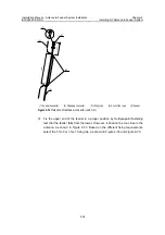
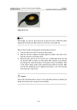
There are two types of waterproof tape needed: waterproof insulation tape and PVC
tape, as shown in Figure 2-41 and Figure 2-42.
Figure 2-41
Waterproof insulation tape

