
55
LP-171 Rev. 3.3.15
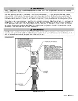
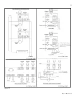
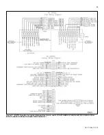
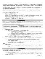
Figure 32
– MC Series Internal Connection Diagram
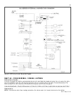
PART 10 – FIELD WIRING – VISION 1 OPTION
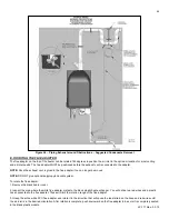
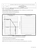
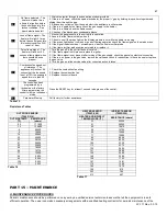
Outdoor Sensor Function
The user can program the desired supply temperature based on the heat transmitter (baseboard, radiant floor, air handler) that will be
used in the installation. Once the outdoor sensor (light green wires) is connected to the control board, the water temperature of the
heater will adjust to run the heater more efficiently and provide greater comfort to the living space.
Connection Specification
– Wire 22 AWG maximum to 100 feet or 18 AWG up to 150 feet. Length of wire run cannot exceed 150 feet.
Outdoor Sensor
NOTE:
If the system requires a fixed operating temperature, the outdoor sensor is not required and should not be installed.
Содержание MC120
Страница 21: ...21 LP 171 Rev 3 3 15 M PIPING DETAILS Figure 5 ...
Страница 53: ...53 LP 171 Rev 3 3 15 Figure 30 ...
Страница 71: ...71 LP 171 Rev 3 3 15 Figure 34 ...
Страница 72: ...72 LP 171 Rev 3 3 15 Figure 35 ...
Страница 73: ...73 LP 171 Rev 3 3 15 Figure 36 ...
Страница 76: ...76 LP 171 Rev 3 3 15 ...
Страница 77: ...77 LP 171 Rev 3 3 15 ...
Страница 78: ...78 LP 171 Rev 3 3 15 MAINTENANCE NOTES ...