
49
LP-171 Rev. 3.3.15
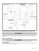
The gas supply shall have a maximum inlet pressure of less than 14" water column (350 mm), ½ pound pressure (3.5 kPa), and a
minimum of 3.5" water column. The entire piping system, gas meter and regulator must be sized properly to prevent pressure drop
greater than 0.5" WC as stated in the National Fuel Gas Code. This information is listed on the rating plate.
NOTE:
Maximum inlet gas pressure must not exceed 14” w.c. (3.5 kPa).
*NOTE:
Installer must supply trap to meet local code requirements.
It is very important that you are connected to the type of gas noted on
the rating plate. “LP” for liquefied petroleum, propane gas, or “NAT” for
natural or city gas. You must not do a gas conversion without an
approved gas conversion kit. Prior to turning the gas on, all gas
connections must be approved by the local gas supplier or utility, in
addition to the governing authority.
A gas conversion kit comes with the heater. Follow the included
instructions VERY carefully. Failure to follow gas conversion
instructions could result in property damage, serious injury, or death.
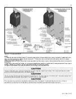
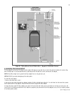
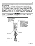
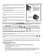
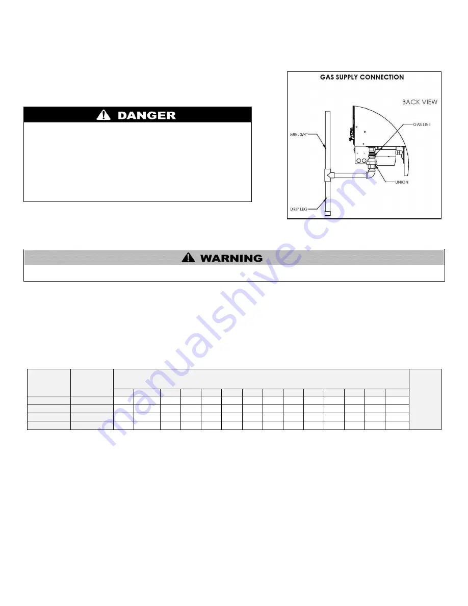
Do not remove the adaptor in Figure 28! It is mandatory that this fitting is used for
connection to a field fabricated drip leg per the National Fuel Gas Code. You must
ensure that the entire gas line to the connection at the heater is no smaller than
¾".
Do not attempt to support the weight of gas piping with the heater or its accessories. The gas valve and blower will not support the
weight of the piping. Failure to follow this warning could result in substantial property damage, severe personal injury, or death.
Once all inspections have been performed, the piping must be leak tested. If the leak test requirement is a higher test pressure than the
maximum gas inlet pressure, you must isolate the heater from the gas line to continue leak testing. To do this, you must turn off the
factory and field-installed gas cocks. This will minimize the possibility of damaging the gas valve. Failure to do so may damage the gas
valve. In the event the gas valve is exposed to a pressure greater than ½ PSI, 14" water column, the gas valve must be replaced. Never
use an open flame (match, lighter, etc.) to check gas connections.
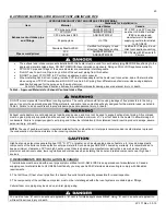
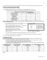
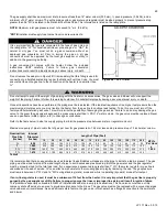
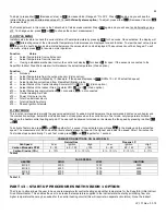
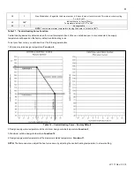
Refer to the table below to size the supply piping to minimize pressure drop between meter or regulator and unit.
Maximum capacity of pipe in cubic feet of gas per hour for gas pressures of .5 psi or less and a pressure drop of .3 inch water column.
Nominal Iron
Pipe Size
(Inches)
Internal
Diameter
(Inches)
Length of Pipe (Feet)
BTU’s
Per Hour
x
1,000
10
20
30
40
50
60
70
80
90
100
125
150
175
200
¾
.824
278
190
152
130
115
105
96
90
84
79
72
64
59
55
1
1.049
520
350
285
245
215
195
180
170
160
150
130
120
110
100
1 ¼
1.380
1,050
730
590
500
440
400
370
350
320
305
275
250
225
210
1 ½
1.610
1,600
1,100
890
760
670
610
560
530
490
460
410
380
350
320
Table 8
It is recommended that a soapy solution be used to detect leaks. Bubbles will appear on the pipe to indicate a leak is present. The gas
piping must be sized for proper flow and length of pipe to avoid excessive pressure drop. Both the gas meter and the gas regulator
must be properly sized for the total gas load. If you experience a pressure drop greater than 1" WC, the meter, regulator or gas line is
undersized or in need of service. You can attach a manometer to the incoming gas drip leg by removing the cap. The gas pressure
must remain between 3.5" WC and 14" WC during stand-by (static) mode and while in operating (dynamic) mode at full output.
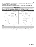
If an in-line regulator is used, it must be a minimum of 10 feet from the heater. It is very important that the gas line is properly
purged by the gas supplier or utility. Failure to properly purge the lines or improper line sizing will result in ignition failure.
This problem is especially noticeable in NEW LP installations and also in empty tank situations. This can also occur when a utility
company shuts off service to an area to provide maintenance to their lines. The gas valve must not be replaced with a conventional gas
valve under any circumstances. As an additional safety feature, the gas valve in this heater has a flanged connection to the swirl plate
and blower.
Figure 28
– LP-171-BB
Содержание MC120
Страница 21: ...21 LP 171 Rev 3 3 15 M PIPING DETAILS Figure 5 ...
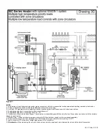
Страница 53: ...53 LP 171 Rev 3 3 15 Figure 30 ...
Страница 71: ...71 LP 171 Rev 3 3 15 Figure 34 ...
Страница 72: ...72 LP 171 Rev 3 3 15 Figure 35 ...
Страница 73: ...73 LP 171 Rev 3 3 15 Figure 36 ...
Страница 76: ...76 LP 171 Rev 3 3 15 ...
Страница 77: ...77 LP 171 Rev 3 3 15 ...
Страница 78: ...78 LP 171 Rev 3 3 15 MAINTENANCE NOTES ...