HTD Lync 12 Скачать руководство пользователя страница 28

28

Addendum: Cat Cable and RJ-45 Plugs

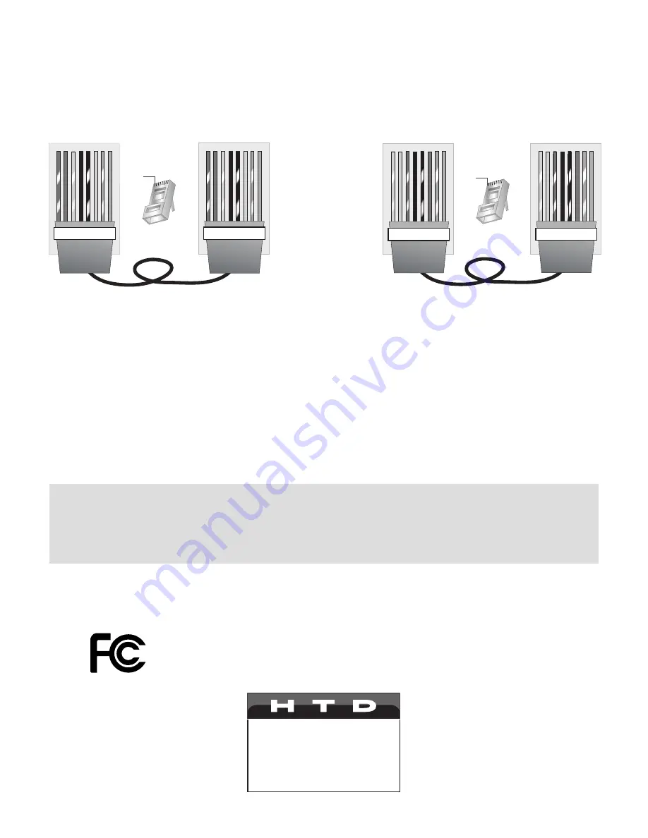
After running Cat cable (Cat 5, Cat5e, Cat6) as needed for your installation, use a crimping tool to attach RJ-45 plugs 

at both ends. Always follow a standard T-568A (recommended) or T568B connection. 

Make sure the same standard 

is used at both ends of the cable

. Never use a “crossover” cable where the two ends of the cable are wired differ-

ently.

Tips for Running Cat Cable and Connecting RJ-45 Plugs:

• 

Do not deform, do not sharply bend, do not stretch, do not staple, do not run parallel with power cables, and do 

not run Cat cables near noise inducing components. 

• 

Leave at least 3 feet of extra cable at a LyncTouch or source input panel location; 6 feet at the central location. Do 

not use a patch panel as they only create an opportunity for mis-wiring. 

• 

If you are pulling cables through holes, it is easier to attach RJ-45 plugs after the cable is pulled.  

• 

At the point where the cable attaches to the RJ-45 plug, no more than 1/2” of the Ethernet cable should remain 

untwisted otherwise it will be susceptible to crosstalk. 

• 

Looking at the RJ-45 plug with the clip facing away from you, pin 1 is on the left and brown is always on the right. 

• 

Odd numbered pins are always striped; even numbered pins are always solid colored. 

Note: A short, pre-terminated Cat cable was included with your system. If you are experiencing an issue with a 

LyncTouch or input panel, try taking that device to the central location and connecting it to the same zone using this 

cable. Restart the Lync 6 or Lync 12 controller. If the device functions correctly here but not within the zone, the most 

common issue is with one end of the long Cat cable being terminated incorrectly. If the problem persists after re-ter-

minating both RJ-45 plugs, it is possible the Cat cable has somehow been damaged. Contact HTD for assistance.

RJ-45 Plug

Clip is pointed

away from you

T-568B

o


O


g   B   b


G   br  BR

1 2 3 4 5 6 7 8

T-568B

o


O


g   B   b


G   br  BR

1 2 3 4 5 6 7 8

RJ-45 Plug

Clip is pointed

away from you

T-568A

1 2 3 4 5 6 7 8

  g   G   o


B   b   O   br 


BR

T-568A

1 2 3 4 5 6 7 8

  g   G   o


B   b   O   br 


BR

O

o

G

g

B

b

BR

br

Orange

Orange striped

Green

Green striped

Blue

Blue striped

Brown

Brown striped

Wire Key

T-568A Straight-Through Cat5 Cable

T-568B Straight-Through Cat5 Cable

Pin 1

Pin 1

This device complies with Part 15 of the FCC Rules. Operation is subjected to the following two conditions: 

   1) this device may not cause harmful interference and, 

   2) this device must accept any interference received,including interference that may cause undesired 

   operation.

Home Theater Direct

Toll free: 866-HTD-AUDIO (483-2834)

www.htd.com

[email protected]

Содержание Lync 12

Страница 1: ...Lync Owner s Manual Toll free 866 HTD AUDIO 483 2834 www htd com info htd com Copyright Home Theater Direct Inc V 12 17 2019...

Страница 2: ...his device during lightning storms Power Cord Protection Route the power cord so that it is not likely to be walked on or pinched by items placed upon or against them paying particular attention to th...

Страница 3: ...ting the Lync 6 Lync 12 to a Multi Channel Amplifier s 11 AmplifierSettings 13 Source Connections at the Central Location 14 Source Input Panel Connections Spread Throughout the Home 14 Making use of...

Страница 4: ...re applicable but many of our customers get up and running quickly by first understanding how cable should be run and then following our Quick Setup instructions on the following page Overview Prepari...

Страница 5: ...e Out to Ch 5 and 6 Zone 6 Variable Out to Ch 11 and 12 7 Confirm that all of the 1 2 Line switches on the multi channel amplifier s are set to Line 8 Connect one audio source into the Source 7 Input...

Страница 6: ...100mA IN OUT System TRIGGER AC DC 3 20V Mute Made in T aiwan CAUTION T o Prevent Electric Shock Do Not Remove Cover No User Serviceable Parts Inside Refer Servicing T o Qualified Service Personnel WAR...

Страница 7: ...6 7 8 9 10 11 12 Zone Status Source Signal Strength AC 120V 60Hz FUSE T2AL 250V Power Consumption 180W ROUTED IR OUT SOURCE INPUT KEYPAD PORTS IR IN 13 SOURCE 13 14 15 16 17 SOURCE 18 MP3 L ZONE 1 PRE...

Страница 8: ...lt in amplification and multiple source inputs For this reason it is not typically set up as a primary zone with variable volume on the whole house audio system However it is possible to connect the f...

Страница 9: ...ne where you wish to add a source input one per LyncTouch The passive Standard Input Panel SIP must be connected to a LyncTouch The Analog Input Panel AIP Bluetooth Input Panel BIP or Digital Input Pa...

Страница 10: ...log Input Panel AIP Bluetooth Input Panel BIP and Digital Input Panel DIP Active devices connect either to an open port on a LyncTouch or an open port on the central Lync controller Note It is possibl...

Страница 11: ...12V Trigger cable 3 Shielded Stereo Patch Cables Speaker Connections Left Left Left Left Left Left Right Right Right Right Right Right Power 1 2 3 4 5 6 1 2 3 4 5 6 7 8 9 10 11 12 Zone Status Source S...

Страница 12: ...ed Service Personnel WARNING T o Prevent Fire Or Shock Hazard Do Not Expose This Unit T o Rain Or Moisture FIXED VARIABLE OUTPUT TO AMP L ZONE 7 PREOUT ZONE 8 PREOUT ZONE 9 PREOUT ZONE 10 PREOUT ZONE...

Страница 13: ...o make it easier to recall which Line Output from the Lync Controller is being sent to each channel Bridge Switch Since you are not bridging the two channels make sure the Bridge Switch is off far lef...

Страница 14: ...Power 1 2 3 4 Zone Status ROUTED IR OUT SOURCE INPUT KEYPAD PORTS 7 8 9 10 11 12 MP3 R L 4 3 2 1 5 6 IR IN RS232 INTERFACE GLOBAL IR OUT 12V D TRIGG 100m IN FIXED VARIABLE SOURCE 7 Power 1 2 3 4 5 6...

Страница 15: ...when it is not selected for that zone 15 How to Connect Making Use of Infrared IR Capability To Whole house Audio Controller To Whole house Audio Controller Use the double sided tape included with the...

Страница 16: ...ove Cover No User Serviceable Parts Inside Refer Servicing T o Qualified Service Personnel WARNING T o Prevent Fire Or Shock Hazard Do Not Expose This Unit T o Rain Or Moisture FIXED VARIABLE IR IN Do...

Страница 17: ...cuit will look similar to the diagram shown below Here s how to wire your Lync Controller into your doorbell circuit Splice 2 conductors of doorbell wire or 2 of the wires in a Cat5e cable from any po...

Страница 18: ...8 digit code that is unique to you Keep this code secure Download the HTD Phone to Zone app NOT the Receive app on every iOS and Android smart de vice on which you d like to be able to initiate a Phon...

Страница 19: ...n Talk into the phone as you normally would and your voice is heard through the speakers in the zone The person within the zone must press the TALK button in order to talk back during which time they...

Страница 20: ...f each amplifier using the button on the front It is not necessary to press the power button on the front of the amplifier if it is already in stand by mode 3 Power off your central Lync controller mo...

Страница 21: ...ouch when they are installed into a wall where the adjoining space is not conditioned such as an attic or exterior wall Mounting into a Surface without a Junction Box or Low Voltage Mounting Ring Lync...

Страница 22: ...e RJ 45 port When this is done be sure to insert an RJ 45 termination plug included with every LyncTouch AIP DIP and BIP into any open port to ensure proper operation Connecting a second LyncTouch wit...

Страница 23: ...F Release the Power Button Quick Key The Quick Key is a button you can customize to allow a single button press to turn on the zone and then activate up to two separate ACTIONS The most common use of...

Страница 24: ...An HTD support rep will instruct when one of these address settings should be used Customize how the display behaves when active and in stand by Level on The brightness level on a scale of 1 to 5 brig...

Страница 25: ...our website and YouTube for this Step 1 Press Wifi Off to activate the WiFi chip embedded in LyncTouch The screen will display WiFi Started If you have previously connected the LyncTouch to your WiFi...

Страница 26: ...f the screen A list of available zones will appear Step 2 Select the zone in which you want to intercom If that zone is currently powered off or in DND mode you will be asked if you would like to turn...

Страница 27: ...then pressing the Talk button for approximately one second and releasing Customize zone and source names with the HTD Lync app Zone names will default to Zone 1 Zone 2 etc and Source names will defaul...

Страница 28: ...even numbered pins are always solid colored Note A short pre terminated Cat cable was included with your system If you are experiencing an issue with a LyncTouch or input panel try taking that device...

Отзывы: