HRW HPE-BNMBUS V401 Manual 180307 E. & O. E. / Subject to change without notice
Page 20 of 24
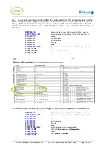
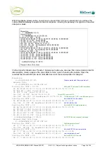
05= DIF 3E VIF 00 ReadData4 X0 00 00 00 00
Flow rate found!
Looking for DVIF = 05
Next
with
DIF
05,
Power
68 77 77 68 08 00 72 50 15 28 08 EE 4D 0D 04 7B 00 00 00
05= DIF 2B VIF 00 ReadData4 X0 00 00 00 00
Power
found!
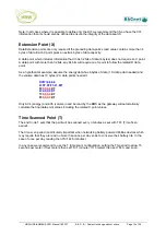
After last configured point is found resolve back to summary display with found results:
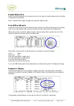
HPE-BNMBUS V4.01 BACnet MBUS
1000) 5 1001)BN = 38400 1002)MBUS = 2400 8E1 DI) 1005 MM) 10 SV) 0
1)Resets = 0 0 5 2)BNErrors = 0 3)MBUSErrors = 18
4)IDNo = P 0 DVIF = 0406 DATAType = 24 Data = 2 S T 17
5) DVIF = 04 DATAType = 24 Data = 254 S T 17
6) DVIF = 05 DATAType = 44 Data = 41C46100 S T
24.547363 17
7) DVIF = 05 DATAType = 44 Data = 41C43500 S T
24.525878 17
8) DVIF = 05 DATAType = 44 Data = 00000000 S T
0.000000 17
9) DVIF = 05 DATAType = 44 Data = 00000000 S T
0.000000 17
Pt No = nn/P,nn,nn,nn,PointType D Diag P = Page No TimeOut = 5 Secs
E MBUS Enabled TS = 1(1)Mins X to exit W to write values
Installation & Commissioning
Power & RS485
This is an RS485 network device designed for indoor use, mounted in a dry electrical panel.
Ideally it should be mounted to the panel backplane in a horizontal position (RJ11 sockets on
the lower side and communications ports on the upper side)
Each 24Vac power supply transformer should have the neutral (24Vac N) connection grounded
at the electrical panel earth connection to ensure the device grounding is at the same potential
as the network master’s grounding
Where more than one device is connected to a common transformer ensure that the 24Vac
phasing is the same to each device (‘A’ connects to ‘A’, ‘N’ connects to ‘N’ in all cases)
If the red comms light adjacent to the RS485 terminals emits an obvious flash every time 24Vac
power is applied to the device then the micro-processor may be corrupted. The micro processor
should be replaced
RS485 multi-drop cable should be used for the network connections, complete with end of line
terminating resistors (120Ω). Belden 9841 or equivalent is recommended. The recommended
cable is a low capacitance twisted pair with braid and foil screen
The RS485 cables should be terminated directly at each device in a daisy-chain configuration,
avoiding ‘laterals’ or ‘spurs’
The RS485 screen should be connected at the network master’s ground terminal. The incoming
and outgoing screen at each device should be continuously connected via the S terminal of the
device (note that the device’s S terminal has no electrical connection to the device, it merely
acts as a junction terminal for the purpose of screen continuity)

