IT3/IT5
Connector System
PWB
A
SSEMBLY
N
OTES
Document Number:
ETAD-F0458
Revision 3.10
Page
40
of
73
The Hirose IT3/IT5 receptacles’ 6mm or 7mm heights allow for high-resolution, low-noise x-ray
imaging. Whether a mounting or mating receptacle, and regardless of the stacking height of
the final assembly, the images remain consistent. No special modifications to the image
analysis routine to compensate for different connector heights are needed.
Unless specifically mentioned, IT3 and IT5 share the same capability and requirement.
9.1 Sampling Frequency
100% of the components should be inspected
for the following defect modes:
•
Solder Bridges
•
Cold Solder Joints
•
Open Solder Joints
•
Cracks
•
Head-In- Pillow*
•
Excessive Voids
* The
appearance
of
head-in-pillow
defects in
ball-on-pin
BGA constructions
differs
slightly
from their typical appearance in
ball-on-pad
constructions. Refer to section 11, Tips for SMT
Assembly for more information on head-in-pillow.
9.2 X-Ray Laminography
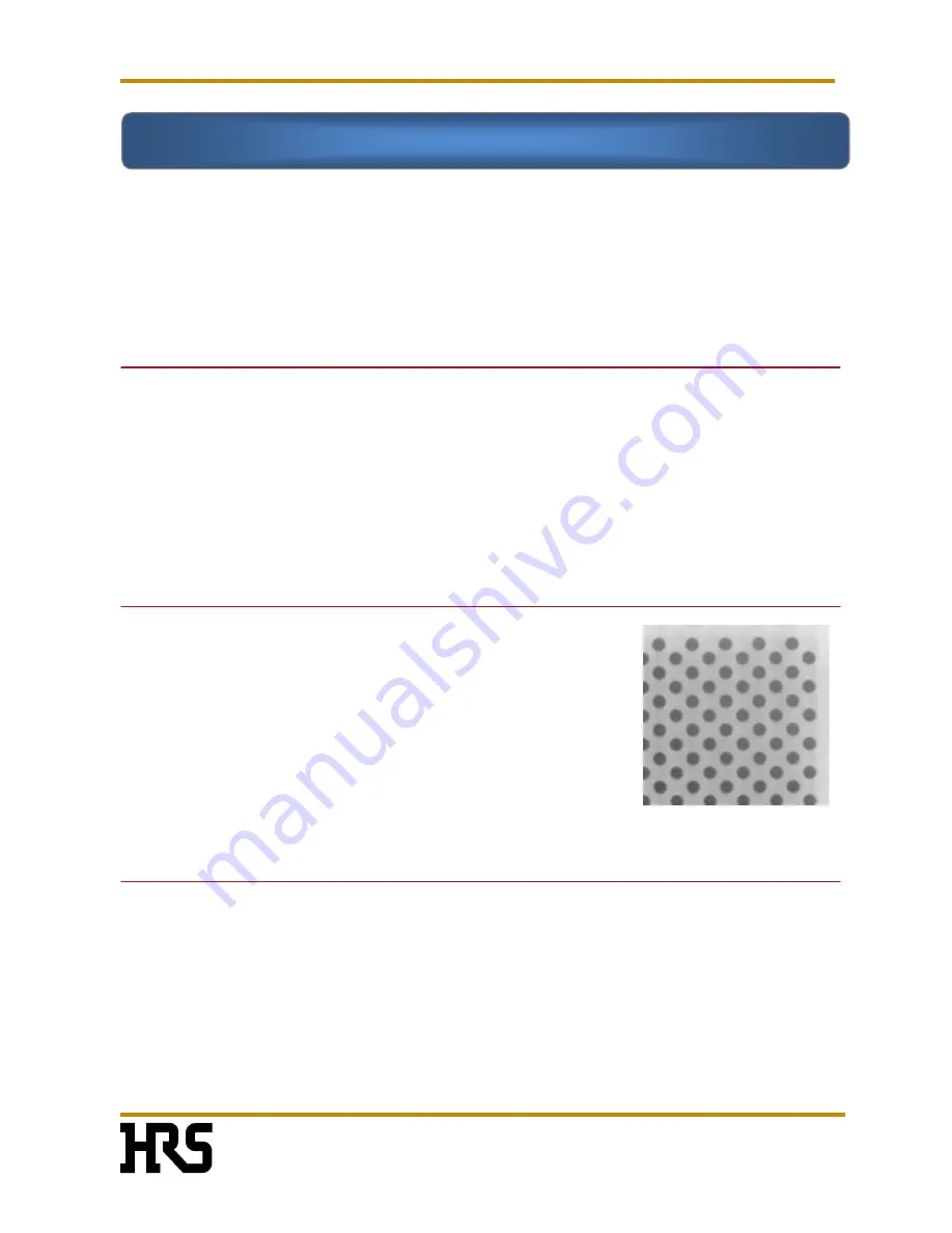
As part of the production process, 3-dimensional x-ray
laminography should be used to inspect the assembly after
reflow processing.
If the automatic inspection system reports potential soldering
defects,
the defects should be verified
by visual inspection
and/or 2-dimensional transmission x-ray inspection with oblique
angle views before beginning the rework procedure.
9.3 Visual Inspection
If the suspected defect is near the outside edge of the receptacle, it may be visible using
optical devices. Visual inspection tools include devices ranging from hand-held mirrors to
digital endoscopes. If the suspected defect is on an interior ball, it may require 2-dimensional
x-ray for verification.
Section 9 Inspection
Nov.1.2022 Copyright 2022 HIROSE ELECTRIC CO., LTD. All Rights Reserved.


