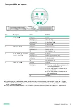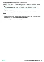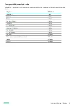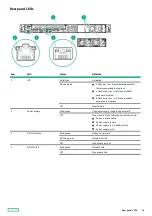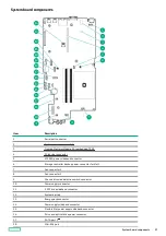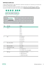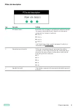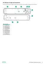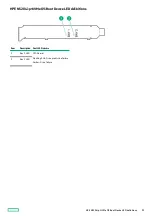
System maintenance switch descriptions
System maintenance switch descriptions
Position
Position
Default
Default
Function
Function
S1
Off
Off = iLO 5 security is enabled.
On = iLO 5 security is disabled.
S2
Off
Reserved
S3
Off
Reserved
S4
Off
Reserved
S5
Off
Off = Power-on password is enabled.
On = Power-on password is disabled.
S6
Off
Off = No function
On = Restore default manufacturing settings
S7
Off
Reserved
S8
—
Reserved
S9
—
Reserved
S10
—
Reserved
S11
—
Reserved
S12
—
Reserved
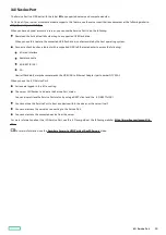
To access the redundant ROM, set S1, S5, and S6 to On.
When the system maintenance switch position 6 is set to the On position, the system is prepared to restore all configuration settings
to their manufacturing defaults.
When the system maintenance switch position 6 is set to the On position and Secure Boot is enabled, some configurations cannot be
restored. For more information, see Configuring security.
1
2
3
System maintenance switch descriptions
19
Содержание ProLiant DL20 Gen10 Plus
Страница 20: ...DIMM slot location The arrow points to the front of the server DIMM slot location 20 ...
Страница 30: ...Fan numbering Fan numbering 30 ...
Страница 100: ...Installing an optical drive in the LFF drive chassis 100 ...
Страница 154: ...Cabling This chapter includes cabling guidelines and diagrams for internal component cabling Cabling 154 ...
Страница 169: ...Energy pack cabling Energy pack cabling 169 ...
Страница 174: ...M 2 SATA SSD add in card cabling 174 ...
Страница 176: ...Fan cabling Color Description Orange Fan 1 cable Blue Fan 2 cable Gold Fan 3 cable Fan cabling 176 ...
Страница 177: ...Chassis intrusion detection switch cabling Chassis intrusion detection switch cabling 177 ...
Страница 178: ...Serial port cabling Serial port cabling 178 ...
Страница 180: ...Power supply cabling 180 ...
Страница 185: ...Troubleshooting NMI functionality Troubleshooting resources Troubleshooting 185 ...
Страница 196: ...Ukraine RoHS material content declaration Ukraine RoHS material content declaration 196 ...

