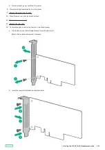
c. Open the riser slot bracket (callouts 1 and 2) and remove the slot blank (callout 3).
Retain the slot blank and the screw for future use.
d. Install the add-in card.
Make sure that the add-in card is seated firmly in the slot.
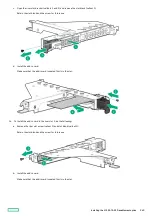
14. To install the add-in card in the riser slot 2, do the following:
a. Remove the riser slot screw (callout 1) and slot blank (callout 2).
Retain the slot blank and the screw for future use.
b. Install the add-in card.
Make sure that the add-in card is seated firmly in the slot.
Installing the M.2 SATA SSD enablement option
140
Содержание ProLiant DL20 Gen10 Plus
Страница 20: ...DIMM slot location The arrow points to the front of the server DIMM slot location 20 ...
Страница 30: ...Fan numbering Fan numbering 30 ...
Страница 100: ...Installing an optical drive in the LFF drive chassis 100 ...
Страница 154: ...Cabling This chapter includes cabling guidelines and diagrams for internal component cabling Cabling 154 ...
Страница 169: ...Energy pack cabling Energy pack cabling 169 ...
Страница 174: ...M 2 SATA SSD add in card cabling 174 ...
Страница 176: ...Fan cabling Color Description Orange Fan 1 cable Blue Fan 2 cable Gold Fan 3 cable Fan cabling 176 ...
Страница 177: ...Chassis intrusion detection switch cabling Chassis intrusion detection switch cabling 177 ...
Страница 178: ...Serial port cabling Serial port cabling 178 ...
Страница 180: ...Power supply cabling 180 ...
Страница 185: ...Troubleshooting NMI functionality Troubleshooting resources Troubleshooting 185 ...
Страница 196: ...Ukraine RoHS material content declaration Ukraine RoHS material content declaration 196 ...


