background image

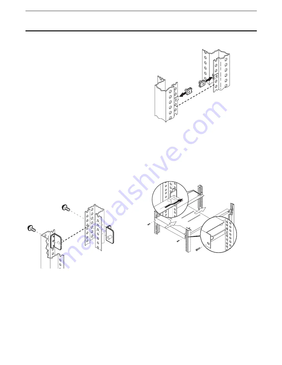
STEP 4

Install Plain Shelf.

Standing in front of the rack and holding the front of
the Plain Shelf, move it to the rear. The pins pointing
in on the Rear Brackets fit into the channels cut into
the back of the Plain Shelf. Align the front of the shelf
at the EIA location.

STEP 5

Install Decorative Screws in front column.

Front holes in the Plain Shelf should align with Sheet
Metal Nuts attached in Step 3. Installation complete.

23

Installation of Rack Accessories

This section provides installation procedures for the HP Rack System/E accessories.

Installing Universal Shelf

This kit requires 1 EIA unit in your HP rack.

Contents

2

Rear Brackets 

2

Sheet Metal Nuts  

1

Plain Shelf  

2

Decorative Screws  

2

Torx 25 Screws with Lock Washers 

Tools Needed:

Torx 25 Driver

NOTE: Extend the rack’s four leveling feet
before installing components in the rack.
Remove side panels to install the Plain Shelf.

STEP 1

Choose EIA location for the Plain Shelf.

Determine the height for the Plain Shelf and locate
EIA number on columns where bottom of Plain Shelf is
to be installed. 

STEP 2

Position and attach Rear Brackets.

Position the bottoms of the Rear Brackets at the
desired EIA location. Install with two non decorative
Torx 25 bolts.

STEP 3

Install Sheet Metal Nuts in front columns.

In the middle hole of the EIA unit located in Step 1,

place sheet metal nuts on the front columns as shown.

(The placement location shown is only an example.)

Chapter 4 

Procedures

EIA location of 
Monitor Base bottom

29

28

27

26 

30

31

32

29

30

31

3

30

31

EIA location of 
MonitorBase bottom

            0

31

30

Содержание System/E25

Страница 1: ...Rack System E User s Manual System E41 System E33 System E25 ...

Страница 2: ...able for errors contained herein or for incidental or consequential damages in connection with the furnishing performance or use of this material This document contains proprietary information that is protected by copyright All rights are reserved No part of this document may be photocopied reproduced or translated to another language without the prior written consent of Hewlett Packard Company He...

Страница 3: ...rom delivery 5 Warranty does not apply to defects resulting from a improper or inadequate maintenance or calibration b software interfacing parts or supplies not supplied by HP c unauthorized modification or misuse d operation outside of the published environmental specifications for the product or e improper site preparation or maintenance 6 TO THE EXTENT ALLOWED BY LOCAL LAW THE ABOVE WARRANTIES...

Страница 4: ...Rack Space 11 Installing Equipment in the Rack 11 Ventilation and Heat Dissipation 11 Installing Rail Mounted Equipment into the Rack 12 Stability 13 4 Procedures 19 Receiving 19 Unpacking Handling and Moving 19 Leveling the Rack 22 Repackaging the Rack for Shipment 22 Installation of Standard Rack Accessories 25 Installing Universal Shelf 25 Installing Keyboard Shelf 26 Installing Monitor Shelf 2...

Страница 5: ...and warnings This product has not been evaluated for connection to an IT power system an AC distribution system having no direct connection to earth ground according to IEC EN60950 Grounding WARNING This is a safety class I product and has a protective earthing grounding terminal There must be an uninterruptable safety earth ground from the main power source to the product s input wiring terminals...

Страница 6: ... THE TOTAL INPUT CURRENT ratings of the equipment installed in the rack to avoid overloading the PDU or any uninterruptable power supply UPS to which it may be connected The output current rating of the PDU equals the output current rating of the power source to which the PDU is connected but not more than the maximum current rating amperage marked on the PDU CHECK THE GROUNDING when installing ra...

Страница 7: ...ded near two columns at the base and another at the top rear Racks heights are measured in meters inches EIA units and U 1 EIA unit equals 1 U which equals 44 45mm 1 75 in The columns are numbered EIA units The U41 rack is 1 96m or 41 EIA units Internally rails and slides that hold your equipment lock into slots in the vertical mounting columns and are sometimes fastened to the columns with screws...

Страница 8: ... foot to rear anti tip foot E25 E33 E41 racks 135 89 cm 53 5 in 1 25m E25 Rack 1 26 m 25U 49 5 in 59 7 cm 23 5 in 92 7 cm 36 5 in 65 kg 144 lbs 1 6m E33 Rack 1 61 m 33U 63 5 in 59 7 cm 23 5 in 92 7 cm 36 5 in 69 kg 153 lbs 1 96m E41 Rack 1 97 m 41U 77 5 in 59 7 cm 23 5 in 92 7 cm 36 5 in 73 5 kg 162 lbs Note Graphite colored racks are only available in 1 6 m and 1 96 m heights The following parts ...

Страница 9: ...upport rails The mounting columns have pre positioned threaded inserts pressed into the hexagonal accessories holes in the front faces of the columns The inserts are positioned to accept tie brackets hinges latches and PDUs Anti Tip Feet A front and rear anti tip foot are included with HP Rack Systems to provide additional stability The anti tip feet must be attached before installing servicing or...

Страница 10: ...cated in each corner to level and stabilize the rack For maxi mum accuracy use a level while adjust ing the feet Rear Door The rear door comes installed from the factory Standard is a right opening per forated rear door with a lockable slam latch and sheetmetal catch providing ventilation and security The rear door can be mounted to open from either the left or the right They are perforated for ma...

Страница 11: ...n be mounted both vertically and horizontally on the rear rack columns depending on your rack configuration If you purchased the bundle containing both the 10 and 16 amp products you can con nect them to each other with the provided cord Use the EIA holes for horizontal mounting and the acces sory holes for vertical mounting Each rack can be equipped with up to six PDUs Each PDU must be purchased ...

Страница 12: ...ils warnings and safety certificate Circuit Protector The PDU is equipped with a circuit protector for each power phase If one phase shorts or overloads one or both of the circuit protectors in the PDU trip Unplug the PDU before trying to locate and correct the electrical problem then reset both circuit protectors on the PDU to restore power to the rack Optional Cables The following option cables ...

Страница 13: ...columns Only after securing a pair of rails with screws can equipment be installed The mounting slots in the columns are positioned to make support rail placement convenient in EIA units Rack Lifting Hooks Four lifting hooks can be fitted to the top of the rack Together they can support the weight of a rack loaded to maximum recommended gross weight Each hook is capable of supporting 248 6 kg 547 ...

Страница 14: ... have lips that fit into the support rails and holes for screws The blocks are slid into contact with the equipment and are then attached to the rail with screws Spacers are fit between the rails and the columns Ballast Ballast is available in 30 lb and 120 lb kits and may be required when using slide mounted products and or keyboard work surface products Use the stability work sheets to determine...

Страница 15: ...d adequate space for the doors to open freely and slide mount ed equipment to be extended Door Clearance The rack requires a minimum of 600 mm 23 6 in for rear door clearance The same amount is required for the front door if installed Cable Access The base of the rack stops 100 mm 3 9 in short of the rear door providing an access path for power and signal cables Installing Equipment in the Rack Tw...

Страница 16: ...k The internal temperature should not exceed the heat rating of any installed instruments Installing Rail Mounted Equipment into the Rack Equipment is installed by first attaching equipment rails between both front and rear columns as shown in Figure 3 2 A clip nut goes behind the rail and a spacer block at the top hole the EIA unit This is the same hole the screw lines up with Figure 3 2 Attachin...

Страница 17: ...ll most likely cancel The center of gravity of the cabinet itself is well below the critical height adding stability Because the racks are deeper than they are wide they are more stable from front to back than side to side as shown in Figure 3 4 Figure 3 3 Critical Height Chapter 3 Installation Guidelines Xí W X Y Z Vertical axis 10 degrees TAN 10 degees 11 0 Z Z 11 0 TAN 10 degrees Z 62 4 in 1 58...

Страница 18: ... than two wheels at a time to minimize the possibility of tipping Keep speed SLOW heavy racks are hard to start moving and hard to stop Exercise common sense and caution when moving ANY equipment configuration Slide Mounted Products Slide mounted products and work surface keyboard products need weight and balance calculations per formed to determine the need for ballast to reduce the risk of cabin...

Страница 19: ... ft M1 Moment on rack with all operator serviceable slide mounted products extended M2 Moment of all fixed and trained personnel serviceable slide mounted products and rack M2 moment calculations assume a 1 00 ft center of gravity for installed products If M1 is less than or equal to M2 no additional counter weight is needed If M1 is greater than M2 use the formulas below to determine the required...

Страница 20: ...ne the need for additional counterweight If there are no work surfaces or keyboard mounting kits in the rack this worksheet can be ignored NOTE No slider products may be withdrawn or extended at the same time the work surface is in use Figure 3 6 Moment Illustration for Work Surface Keyboard NOTE Always ensure leveling feet have been deployed 16 Chapter 3 Installation Guidelines ...

Страница 21: ...ied at D ft M2 Moment of all fixed and trained personnel serviceable slide mounted products M2 moment calculations assume a 1 00 ft center of gravity for installed products If M1 is less than or equal to M2 no additional counter weight is needed If M1 is greater than M2 use the formulas below to determine the required counter weight Determine required counter weight if M1 is greater than M2 Force ...

Страница 22: ...18 Chapter 3 Installation Guidelines ...

Страница 23: ...idth Depth Weight 1 25m E25 Rack 1 48 m 58 5 in 1 016 m 40 in 1 22 m 48 in 124 5 kg 274 lbs 1 6m E33 Rack 1 84 m 72 5 in 1 016 m 40 in 1 22 m 48 in 133 2 kg 293 lbs 1 96m E41 Rack 2 2 m 86 5 in 1 016 m 40 in 1 22 m 48 in 142 7 kg 314 lbs Unpackaged 1 25m E25 Rack 1 26 m 25U 49 5 in 59 7 cm 23 5 in 92 7 cm 36 5 in 65 kg 144 lbs 1 6m E33 Rack 1 61 m 33U 63 5 in 59 7 cm 23 5 in 92 7 cm 36 5 in 69 kg ...

Страница 24: ...rdboard top cap from the shipping box 3 Remove the corrugated wrap from the pallet 4 Remove the packing materials 5 Remove four bolts holding down the ramps and remove the ramps 6 Remove the six bolts from the base attaching the rack to the pallet 20 Chapter 4 Procedures ...

Страница 25: ...e ramp requires two people WARNING Make sure that the leveling feet on the rack are raised before you roll the rack down the ramp and any time you roll the rack on the casters Secure the Rack Once in position secure and stabilize your rack using the leveling feet at the corners of the base Chapter 4 Procedures 3 ...

Страница 26: ...hecklist below and refer to the unpacking instructions for details 1 Assemble the original HP packing materials or contact your local Hewlett Packard Sales and Support office 2 Connect the loading ramp to the pallet 3 Raise the leveling feet 4 Push the rack up the ramp front first 5 Secure the rack to the pallet 6 Place the anti static bag over the rack 7 Place the top pad packing material and loa...

Страница 27: ... Decorative Screws 2 Torx 25 Screws with Lock Washers Tools Needed Torx 25 Driver NOTE Extend the rack s four leveling feet before installing components in the rack Remove side panels to install the Plain Shelf STEP 1 Choose EIA location for the Plain Shelf Determine the height for the Plain Shelf and locate EIA number on columns where bottom of Plain Shelf is to be installed STEP 2 Position and a...

Страница 28: ... Clips Tools Needed Torx 25 Driver NOTE Extend the rack s four leveling feet before installing components in the rack STEP 1 Choose EIA location for the keyboard Determine whether the operator will sit or stand while using the keyboard and locate the EIA unit that places the bottom of the Keyboard Tray at the correct height STEP 2 Position and attach Rear Brackets Position the bottoms of the Rear ...

Страница 29: ...e this instruction label Install keyboard and mouse Install cable guide Route the mouse cable through the guide Use the spare cable clips as necessary Installation complete 25 Chapter 4 Procedures Cable gui de Keyboard Instructions Remove label after reading instructions ...

Страница 30: ...tall other components and keyboard kit before installing this Monitor Rack Mount Kit This kit requires 11 EIA units in your HP rack Contents 2 Rear Brackets 6 Sheet Metal Nuts 1 Monitor Base 6 Decorative Screws 2 Torx 25 Screws with Lock 2 Decorative Panels 4 Clamp Assemblies Tools Needed Torx 25 Driver NOTE Extend the rack s four leveling feet before installing components in the rack STEP 1 Choos...

Страница 31: ...column Align the tray as shown Install decorative screws in front into Clip Nuts installed in Step 3 STEP 6 Install Monitor After reading this instruction remove this instruc tion label Install the monitor from the side or rear of the rack Position Clamp Assemblies to secure monitor and tighten 27 Chapter 4 Procedures 29 28 27 26 25 30 31 32 29 30 31 Gray Screws Clamp Assemblies Sheet Metal Nuts ...

Страница 32: ... Each Filler Panel covers 1 EIA unit Contents 6 Filler Panels Tools Needed None STEP 1 Snap into place The Filler Panels snap onto the front columns Each Filler Panel covers 1 EIA Position each panel in a set of EIA holes and push Centeredon EIA unit ...

Страница 33: ... the columns The correct bolts are positioned on the side of the columns facing away from the rack STEP 3 Remove bolts and attach hooks One column at a time remove the two bolts position the lifting hook and bolt the lifting hook to the rack Don t remove more than two bolts at a time STEP 4 Lift rack CAUTION Use all four hooks to lift the rack Do not exceed 547lb per hook STEP 5 Remove the lifting...

Страница 34: ... to the EIA unit where you want to install the spacer Each EIA unit is numbered on the columns of the grey column rack STEP 2 Install Sheet Metal Nuts Place sheet metal nuts over the top hole of the target EIA unit on columns Place the nuts with the protru sion away from the spacer STEP 3 Position the Spacers Position all required spacers There must be a sheet metal nut on the columns behind each ...

Страница 35: ...ront column has threaded inserts positioned to accept machine screws at the 11th and 15th holes down from the top and the 6th and 10th holes up from the bottom Position the hinges on the left column and and secure with machine screws Chapter 4 Procedures STEP 3 Install the latch catch The right front column has pre installed threaded inserts positioned to accept latch bolts at these locations 1 96...

Страница 36: ...ase of each column Attach the ground connector with two nuts Connect the ground cable to the male connector STEP 7 Re energize Re energize the equipment if necessary Installation complete STEP 5 Install the latch assembly The door has openings for the latch catch Remove any installed cover plate insert the latch catch position the backing plate and secure with screws 32 Chapter 4 Procedures ...

Страница 37: ...5 Driver for machine screws New style Use these instructions for attaching the Cable Guide to the new style numbered columns shown below Option A Vertical attachment Align Cable Guide so the attachment points lie over threaded inserts Secure with machine screws and Torx 25 driver Chapter 4 Procedures Option B Horizontal attachment Install sheet metal nuts over desired holes in both columns Secure ...

Страница 38: ...rts are positioned at attachment points secure the Cable Guide with machine screws NOTE If you push the screw into the fas tener before attaching to the rack column the fastener will expand making it difficult to attach the cable guide to the rack 34 Chapter 4 Procedures Attach Cable Guide to these holes Option B Horizontal attachment Install sheet metal nuts over desired holes in both columns Sec...

Страница 39: ...t the bottom of the rack Position the nine EIA units so the tab fits into the lowest column hole that will accept it STEP 2 Push The Side Panels snap into place with a small push Hook the rear of the Side Panel into place and press onto the front column STEP 3 Install all remaining Side Panels The Side Panels all install the same way There are no gaps between panels when properly installed Chapter...

Страница 40: ...m rack Holes 22 and 26 1 6m rack Holes 30 and 34 1 96m rack Holes 38 and 42 Reversing Rear Door Tools needed Torx 25 Driver NOTE Extend the rack s four leveling feet before installing the door NOTE Problems with cable guides tie together kits and PDUs which interfere with reversing the door must be solved on a case by case basis Generally reversing everything on the rear columns is a workable solu...

Страница 41: ... upside down Open the door to approximately 45 degrees and lower the door pins into the two hinges STEP 6 Reconnect grounding strap Reconnect the grounding strap between the door and the rack STEP 7 Reenergize equipment Chapter 4 Procedures 41 ...

Страница 42: ... to change without notice Copyright Hewlett Packard Company 2003 All Rights Reserved Reproductions adaptations or translation without prior written permission is prohibited except as allowed under the copyright laws Part Number 5967 6409 Revised 05 03 ...

Отзывы: