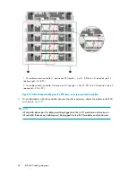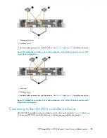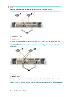
1. This cable connects controller 1, device port 1B (top left — Cntrl 1, DP1B) to I/O module B, port 2
(bottom right - I/O B, P2).
2. This cable connects controller 2, device port 1A (top right — Cntrl 2, DP1A) to I/O module A, port 2
(bottom left - I/O A, P2).
Figure 22 Fibre Channel cabling for the EVA (rear view, top-mounted controller)
2.
For configurations with the controller
between
the disk enclosures, attach the cables to the EVA
as shown in
NOTE:
All controller device port A cabling must be plugged into the A I/O modules on all enclosures.
All controller B device port cabling must be plugged into the B I/O modules on all enclosures.
EVA4400 cabling diagrams
82
Содержание StorageWorks 4400
Страница 15: ...Figure 3 Installation checklist HP StorageWorks 4400 Enterprise Virtual Array installation guide 15 ...
Страница 16: ...Figure 4 Installation checklist cont d About this guide 16 ...
Страница 20: ...Review and confirm your plans 20 ...
Страница 24: ...Remove product from packaging 24 ...
Страница 36: ...Connect cables and power cords 36 ...
Страница 48: ...Configuring management servers using HP SmartStart EVA Storage 48 ...
Страница 50: ...Configuring application servers for Windows using HP SmartStart EVA Storage 50 ...
Страница 78: ...Configuring non Windows application servers 78 ...

