background image

Component

(4)

Model number (select models only)

(5)

Revision number

Regulatory label(s)—Provide(s) regulatory information about the computer.

Wireless certification label(s)—Provide(s) information about optional wireless devices and the

approval markings for the countries or regions in which the devices have been approved for use.

Labels

15

Содержание Spectre 13

Страница 1: ...HP Spectre 13 Pro Ultrabook and HP Spectre 13 Ultrabook Maintenance and Service Guide IMPORTANT This document is intended for HP authorized service providers only ...

Страница 2: ...poration SD Logo is a trademark of its proprietor The information contained herein is subject to change without notice The only warranties for HP products and services are set forth in the express warranty statements accompanying such products and services Nothing herein should be construed as constituting an additional warranty HP shall not be liable for technical or editorial errors or omissions...

Страница 3: ...w another hard surface such as an adjoining optional printer or a soft surface such as pillows or rugs or clothing to block airflow Also do not allow the AC adapter to contact the skin or a soft surface such as pillows or rugs or clothing during operation The device and the AC adapter comply with the user accessible surface temperature limits defined by the International Standard for Safety of Inf...

Страница 4: ...iv Safety warning notice ...

Страница 5: ...6 Computer major components 16 Rubber Kit 18 Mass storage devices 18 Miscellaneous parts 19 Sequential part number listing 20 4 Removal and replacement procedures 23 Preliminary replacement requirements 23 Tools required 23 Service considerations 23 Plastic parts 23 Cables and connectors 23 Drive handling 24 Grounding guidelines 24 Electrostatic discharge damage 24 Packaging and transporting guide...

Страница 6: ...wnloading a BIOS update 58 Using HP PC Hardware Diagnostics UEFI 59 Downloading HP PC Hardware Diagnostics UEFI to a USB device 59 6 Specifications 60 Computer specifications 60 13 3 inch FHD display specifications 61 13 3 inch QHD display specifications 62 7 Backing up restoring and recovering 63 Creating recovery media and backups 63 Creating HP Recovery media 63 Restore and recovery 65 Recoveri...

Страница 7: ...8 Power cord set requirements 68 Requirements for all countries 68 Requirements for specific countries and regions 69 9 Recycling 70 Index 71 vii ...

Страница 8: ...viii ...

Страница 9: ... Supports HD Decode DX11 and HDMI Panel Flush glass design touchscreen multitouch enabled 340 nits 33 8 cm 13 3 in display WLED full high definition FHD 1920x1080 BrightView 2 85 mm UWVA eDP 1 2 at 72 Color Gamut 33 8 cm 13 3 in display WLED Quad High Definition QHD 2560x1440 BrightView 2 55 mm UWVA eDP1 3 PSR at 72 Color Gamut Memory No customer accessible upgradable memory module slots DDR3L 160...

Страница 10: ...ault for Indonesia Russia and Ukraine External expansion cards HP Multi Format Digital Media Card Reader Supports SD SDHC SDXC Push push insertion removal Internal expansion cards One NGFF slot 2230 for WLAN One NGFF slot 2280 for SSD Ports Headphone output and microphone input combo jack stereo One mini Display Port supporting 2560x1600 max 3200x2000 60 Hz resolution Supports HP USB Boost Sleep a...

Страница 11: ...dapter 4 5mm barrel connector 1 8 M length AC and DC power cords 4 cell battery 51 WHr Security Intel AT p Ready support Kensington Security Lock Trust Platfom Module TPM support Operating system Windows 8 1 Serviceability End user replaceable part AC adapter 3 ...

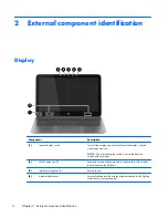
Страница 12: ...The internal display switch is not visible from the outside of the computer 2 WLAN antennas 2 Send and receive wireless signals to communicate with wireless local area networks WLANs 3 Internal microphones 2 Record sound 4 Ambient light sensor Automatically adjusts the display brightness based on the lighting conditions in your environment 4 Chapter 2 External component identification ...

Страница 13: ...f applications 6 Webcam light On The webcam is in use The antennas are not visible from the outside of the computer For optimal transmission keep the areas immediately around the antennas free from obstructions For wireless regulatory notices see the section of the Regulatory Safety and Environmental Notices that applies to your country or region To access this guide from the Start screen type sup...

Страница 14: ...ects or activates items on the screen NOTE The TouchPad also supports edge swipe gestures 3 Left TouchPad button Functions like the left button on an external mouse 4 Right TouchPad button Functions like the right button on an external mouse 5 Right control zone Textured area that allows you to perform additional gestures 6 Chapter 2 External component identification ...

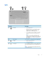
Страница 15: ...or select models the Intel Rapid Start Technology feature is enabled at the factory Rapid Start Technology allows your computer to resume quickly from inactivity 2 Caps lock light On Caps lock is on switching the keys to all capital letters 3 Mute light Amber Computer sound is off Off Computer sound is on 4 Wireless light On An integrated wireless device such as a wireless local area network WLAN ...

Страница 16: ...n results in the loss of unsaved information If the computer has stopped responding and Windows shutdown procedures are ineffective press and hold the power button down for at least 5 seconds to turn off the computer NOTE For select models the Intel Rapid Start Technology feature is enabled at the factory Rapid Start Technology allows your computer to resume quickly from inactivity To learn more a...

Страница 17: ...tem functions when pressed in combination with the esc key 3 Windows key Returns you to the Start screen from any app or window NOTE Pressing the Windows key again will return you to the most recent app that you had open 4 Action keys Execute frequently used system functions 5 Windows applications key Reveals options for a selected object Top 9 ...

Страница 18: ...is off 3 Audio out headphone Audio in microphone combo jack Connects optional powered stereo speakers headphones earbuds a headset or a television audio cable Also connects an optional headset microphone This jack does not support optional microphone only devices WARNING To reduce the risk of personal injury adjust the volume before putting on headphones earbuds or a headset For additional safety ...

Страница 19: ...re or access information To insert hold the card label side up with connectors facing the slot and press in on the card until it is firmly seated To remove press in on the card and quickly release it The card pops out 5 Hard drive light Blinking white The hard drive is being accessed Left side 11 ...

Страница 20: ...models of cell phones and MP3 players even when the computer is off 2 Mini DisplayPort Connects an optional digital display device such as a high performance monitor or projector 3 HDMI port Connects an optional video or audio device such as a high definition television any compatible digital or audio component or a high speed HDMI device 4 AC adapter light On The AC adapter is connected and the b...

Страница 21: ...rflow to cool internal components NOTE The computer fan starts up automatically to cool internal components and prevent overheating It is normal for the internal fan to cycle on and off during routine operation 2 Speakers 2 Produce sound Bottom 13 ...

Страница 22: ...ant information to identify your computer When contacting support you will probably be asked for the serial number and possibly for the product number or the model number Locate these numbers before you contact support NOTE Your service labels will resemble one of the examples shown below Refer to the illustration that most closely matches the service label on your computer Component 1 Product nam...

Страница 23: ...gulatory label s Provide s regulatory information about the computer Wireless certification label s Provide s information about optional wireless devices and the approval markings for the countries or regions in which the devices have been approved for use Labels 15 ...
Страница 24: ...3 Illustrated parts catalog Computer major components 16 Chapter 3 Illustrated parts catalog ...

Страница 25: ...bo Adapter 735532 001 Intel Dual Band Wireless N 7260AN 802 11a b g n 2 2 WiFi BT 4 0 Combo Adapter for use only on HP Spectre 13 Pro Ultrabook computer models 717381 005 9 Solid state drive mSATA 512 MB 744380 001 256 MB 744379 001 128 MB 744378 001 10 System board includes replacement thermal material Intel Core i7 4500U processor and 8 GB system memory for use in models with non Windows 8 opera...

Страница 26: ...ndows 8 Standard operating systems 743851 501 Intel Core i5 4200U processor and 8 GB system memory for use in models with Windows 8 Professional operating systems 743851 001 11 Power button board 744370 001 12 Power connector cable 744362 001 13 Speaker assembly includes cable 744377 001 14 Battery 4 cell 51 Wh 3 42 Ah 734998 001 15 Bottom cover 744360 001 Rubber Kit Item Component Spare part numb...

Страница 27: ...For use in Denmark 490371 081 For use in Europe 490371 021 For use in Israel 490371 BB1 For use in North America 490371 001 For use in South Korea 490371 AD1 For use in Switzerland 490371 111 For use in the United Kingdom and Singapore 490371 031 For use only on HP Spectre 13 Pro Ultrabook computer models For use in India 490371 D61 For use in Japan 490371 291 For use in the People s Republic of C...

Страница 28: ... 490371 BB1 Power cord for use on all computer models in Israel 3 pin black 1 83 m 490371 D61 Power cord for use only on HP Spectre 13 Pro Ultrabook computer models in India 3 pin black 1 83 m 701943 001 HDMI to VGA Adapter 704927 001 RJ 45 to USB adapter 710663 001 Intel Dual Band Wireless AC 7260 802 11 AC 2x2 WiFi BT 4 0 Combo Adapter 717381 005 Intel Dual Band Wireless N 7260AN 802 11a b g n 2...

Страница 29: ...use in Portugal includes keyboard cable and screws 743897 141 Keyboard with for use in Turkey includes keyboard cable and screws 743897 151 Keyboard for use in Greece includes keyboard cable and screws 743897 161 Keyboard for use in Latin America includes keyboard cable and screws 743897 171 Keyboard for use in Saudi Arabia includes keyboard cable and screws 743897 251 Keyboard for use in Russia i...

Страница 30: ...bber Kit includes bottom feet 744376 001 Screw Kit 744377 001 Speaker assembly includes cable 744378 001 128 GB mSATA solid state drive 744379 001 256 GB mSATA solid state drive 744380 001 512 GB mSATA solid state drive 744381 001 Top cover for use in the United States 744382 001 Top cover for use in the United Kingdom 744892 001 45 W HP Smart AC adapter 22 Chapter 3 Illustrated parts catalog ...

Страница 31: ...reassembly can damage plastic parts Use care when handling the plastic parts Apply pressure only at the points designated in the maintenance instructions Cables and connectors CAUTION When servicing the computer be sure that cables are placed in their proper locations during the reassembly process Improper cable placement can damage the computer Cables must be handled with extreme care to avoid da...

Страница 32: ...ng an internal hard drive to products that have magnetic fields such as monitors or speakers Avoid exposing a drive to temperature extremes or liquids If a drive must be mailed place the drive in a bubble pack mailer or other suitable form of protective packaging and label the package FRAGILE Grounding guidelines Electrostatic discharge damage Electronic components are sensitive to electrostatic d...

Страница 33: ...The following table shows how humidity affects the electrostatic voltage levels generated by different activities CAUTION A product can be degraded by as little as 700 V Typical electrostatic voltage levels Relative humidity Event 10 40 55 Walking across carpet 35 000 V 15 000 V 7 500 V Walking across vinyl floor 12 000 V 5 000 V 3 000 V Motions of bench worker 6 000 V 800 V 400 V Removing DIPS fr...
Страница 34: ...nd that proper materials are selected to avoid static charging When grounding is not possible use an ionizer to dissipate electric charges Workstation guidelines Follow these grounding workstation guidelines Cover the workstation with approved static shielding material Use a wrist strap connected to a properly grounded work surface and use properly grounded tools and equipment Use conductive field...

Страница 35: ...ance between the operator and ground To be effective the conductive must be worn in contact with the skin The following grounding equipment is recommended to prevent electrostatic damage Antistatic tape Antistatic smocks aprons and sleeve protectors Conductive bins and other assembly or soldering aids Nonconductive foam Conductive tabletop workstations with ground cords of one megohm resistance St...

Страница 36: ... feet follow these steps 1 Turn off the computer If you are unsure whether the computer is off or in Hibernation turn the computer on and then shut it down through the operating system 2 Disconnect the power from the computer by unplugging the power cord from the computer 3 Disconnect all external devices from the computer Remove the feet 1 Position the computer upside down 2 Lift pry to disengage...

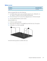
Страница 37: ...through the operating system 2 Disconnect the power from the computer by unplugging the power cord from the computer 3 Disconnect all external devices from the computer Remove the bottom cover 1 Position the computer upside down 2 Remove the 8 Torx T5M2 0 3 0 screws 1 that secure the bottom cover to the computer 3 Lift the bottom cover off the computer 2 Reverse the removal procedures to install t...

Страница 38: ...en shut it down through the operating system 2 Disconnect all external devices connected to the computer 3 Disconnect the power from the computer by first unplugging the power cord from the AC outlet and then unplugging the AC adapter from the computer 4 Remove the bottom cover see Bottom cover on page 29 5 Disconnect the battery Remove the solid state drive 1 Remove the Phillips PM2 0 3 0 screw 1...

Страница 39: ...2 Pull the drive out of the socket 2 Reverse this procedure to install the solid state drive Component replacement procedures 31 ...

Страница 40: ...se in the computer by the governmental agency that regulates wireless devices in your country or region If you replace the module and then receive a warning message remove the module to restore device functionality and then contact technical support Before removing the WLAN module follow these steps 1 Turn off the computer If you are unsure whether the computer is off or in Hibernation turn the co...

Страница 41: ...cable connects to the middle terminal on the WLAN module 2 Remove the Phillips PM2 0 3 0 screw 2 that secures the WLAN module to the base enclosure 3 Remove the WLAN module 3 by pulling the module away from the slot NOTE WLAN modules are designed with a notch to prevent incorrect insertion NOTE If the WLAN antennas are not connected to the terminals on the WLAN module the protective sleeves must b...

Страница 42: ...mputer on and then shut it down through the operating system 2 Disconnect the power from the computer by unplugging the power cord from the computer 3 Disconnect all external devices from the computer 4 Remove the bottom cover see Bottom cover on page 29 5 Disconnect the battery 6 Disconnect the antennas from the WLAN module see WLAN module on page 32 Remove the display assembly 1 Remove the Mylar...

Страница 43: ...and then separate the display from the computer 2 5 If it is necessary to remove the clutch cover or the display hinges a Remove the clutch cover the plastic piece on the bottom of the display by pulling it straight up to disengage it 1 b Remove the 4 Phillips PM2 5 5 0 screws 2 from each hinge that secure the hinges to the display c Remove the antennas and the control cable from the left hinge 2 ...

Страница 44: ...ble from the right hinge 3 and the control cable from the left hinge 4 e Lift the hinges from the display 5 Reverse this procedure to reassemble and install the display assembly 36 Chapter 4 Removal and replacement procedures ...

Страница 45: ...ough the operating system 2 Disconnect the power from the computer by unplugging the power cord from the computer 3 Disconnect all external devices from the computer 4 Remove the bottom cover see Bottom cover on page 29 5 Disconnect the battery Remove the speaker assembly 1 Disconnect the speaker cable from the system board 1 2 Remove the Mylar from atop the wire between the speakers 2 3 Remove on...

Страница 46: ...4 Lift the speakers 4 from the computer Reverse this procedure to install the speaker assembly 38 Chapter 4 Removal and replacement procedures ...

Страница 47: ...it down through the operating system 2 Disconnect the power from the computer by unplugging the power cord from the computer 3 Disconnect all external devices from the computer 4 Remove the bottom cover see Bottom cover on page 29 5 Disconnect the battery Remove the touchpad 1 Disconnect the touchpad cable from the system board 1 2 Remove the 5 Phillips PM1 0 2 0 screws 2 that secure the touchpad ...

Страница 48: ...3 Lift the touchpad straight up and off the top cover 3 Reverse this procedure to install the touchpad 40 Chapter 4 Removal and replacement procedures ...

Страница 49: ... down through the operating system 2 Disconnect the power from the computer by unplugging the power cord from the computer 3 Disconnect all external devices from the computer 4 Remove the bottom cover see Bottom cover on page 29 5 Disconnect the battery Remove the fan 1 Disconnect the fan cable 1 from the system board 2 Loosen the 3 Phillips PM2 0 3 0 screws 2 that secure the fan to the computer C...

Страница 50: ...3 Remove the fan 3 from the computer Reverse this procedure to install the fan 42 Chapter 4 Removal and replacement procedures ...

Страница 51: ...llow these steps 1 Turn off the computer If you are unsure whether the computer is off or in Hibernation turn the computer on and then shut it down through the operating system 2 Disconnect the power from the computer by unplugging the power cord from the computer 3 Disconnect all external devices from the computer 4 Remove the bottom cover see Bottom cover on page 29 5 Disconnect the battery Comp...

Страница 52: ...l equipped with a graphics subsystem with discrete memory NOTE The thermal material must be thoroughly cleaned from the surfaces of the heat sink and the system board components each time the heat sink is removed Replacement thermal material is included with the heat sink and system board spare part kits Thermal grease is used on the processor 1 and the heat sink section 2 that services it 44 Chap...

Страница 53: ...Reverse this procedure to install the heat sink Component replacement procedures 45 ...

Страница 54: ...sconnect all external devices from the computer 4 Remove the bottom cover see Bottom cover on page 29 Remove the battery 1 Disconnect the battery cable from the system board 1 2 Remove the Mylar from atop the broadhead screw near the top of the battery 2 3 Remove the 2 Phillips PM2 0 3 0 broadhead screws 3 that secure the battery to the computer 4 Remove the 2 Phillips PM2 0 4 0 screws 4 that secu...

Страница 55: ...6 Remove the battery from the computer 6 Remove the removal procedure to install the battery Component replacement procedures 47 ...

Страница 56: ...ystem memory for use in models with Windows 8 Professional operating systems 743850 601 System board with Intel Core i5 4200U processor and 8 GB system memory for use in models with non Windows 8 operating systems 743851 001 System board with Intel Core i5 4200U processor and 8 GB system memory for use in models with Windows 8 Standard operating systems 743851 501 System board with Intel Core i5 4...

Страница 57: ...wer button board cable 6 Speaker cable 7 Control cable 2 Lift the Mylar tape 1 to gain access to one of the screws 2 3 Remove the 4 Phillips PM2 0 3 0 screws 2 that secure the system board to the computer 4 Remove the Phillips PM2 0 3 0 broadhead screw 3 that secures the system board to the computer 5 Lift the left side of the board 4 Component replacement procedures 49 ...

Страница 58: ...6 Pull the board up and away toward the left 5 Reverse this procedure to install the system board 50 Chapter 4 Removal and replacement procedures ...

Страница 59: ... Disconnect all external devices from the computer 4 Remove the following components a Bottom cover see Bottom cover on page 29 b Battery see Battery on page 46 c WLAN module see WLAN module on page 32 d Fan see Fan on page 41 e System board see System board on page 48 Remove the power connector cable 1 Remove the Phillips PM2 0 3 0 screw 1 that secures the power connector cable to the computer 2 ...

Страница 60: ...by unplugging the power cord from the computer 3 Disconnect all external devices from the computer 4 Remove the following components a Bottom cover see Bottom cover on page 29 b Battery see Battery on page 46 c WLAN module see WLAN module on page 32 d Fan see Fan on page 41 e System board see System board on page 48 Remove the power button board 1 Remove the Phillips PM2 0 3 0 screw 1 that secures...

Страница 61: ...3 Remove the power button board from the computer 3 Reverse this procedure to install the power button board Component replacement procedures 53 ...

Страница 62: ...he power from the computer by unplugging the power cord from the computer 3 Disconnect all external devices from the computer 4 Remove the following components a Bottom cover see Bottom cover on page 29 b Battery see Battery on page 46 c WLAN module see WLAN module on page 32 d Fan see Fan on page 41 e System board see System board on page 48 Separate the keyboard from the top cover 1 Lift the tap...

Страница 63: ...e top cover 1 5 Remove the 47 Phillips PM1 0 2 0 screws 2 that secure the keyboard to the top cover NOTE Only one screw is shown in the following image but you must remove 47 screws to remove the keyboard Screw locations are shown as while dots on the keyboard in the following image Component replacement procedures 55 ...

Страница 64: ...6 Separate the keyboard from the top cover 3 7 Remove the keyboard Reverse this procedure to install the keyboard 56 Chapter 4 Removal and replacement procedures ...

Страница 65: ...t BIOS updates on the HP website are packaged in compressed files called SoftPaqs Some download packages contain a file named Readme txt which contains information regarding installing and troubleshooting the file Determining the BIOS version To determine whether available BIOS updates contain later BIOS versions than those currently installed on the computer you need to know the version of the sy...

Страница 66: ...n to locate the update later after it has been downloaded to your hard drive b Follow the on screen instructions to download your selection to the hard drive If the update is more recent than your BIOS make a note of the path to the location on your hard drive where the BIOS update is downloaded You will need to access this path when you are ready to install the update NOTE If you connect your com...

Страница 67: ...rdware Diagnostics UEFI tool to a USB drive see Downloading HP PC Hardware Diagnostics UEFI to a USB device on page 59 b Hard drive c BIOS 2 When the diagnostic tool opens click the type of diagnostic test you want to run and then follow the on screen instructions NOTE If you need to stop a diagnostic test press esc Downloading HP PC Hardware Diagnostics UEFI to a USB device NOTE Instructions for ...

Страница 68: ...perature Operating 5 C to 35 C 41 F to 95 F Nonoperating 20 C to 60 C 4 F to 140 F Relative humidity noncondensing Operating 10 to 90 Nonoperating 5 to 95 Maximum altitude unpressurized Operating 15 m to 3 048 m 50 ft to 10 000 ft Nonoperating 15 m to 12 192 m 50 ft to 40 000 ft NOTE Applicable product safety standards specify thermal limits for plastic surfaces The device operates well within thi...

Страница 69: ...er of colors 16 777 216 Contrast ratio 700 1 typical Brightness 340 nits typical Pixel resolution Pitch 0 1529 H x 0 1529 V mm Format FHD 1920 x 1080 Configuration RGB vertical stripe Backlight LED Total power consumption Total 6 10 W Max cell 1 15W Max BL 4 95 W Max Viewing angle 89 horizontal 89 vertical typical 13 3 inch FHD display specifications 61 ...

Страница 70: ...0 Number of colors 16 777 216 Contrast ratio 700 1 typical Brightness 340 nits typical Pixel resolution Pitch 0 1146 H x 0 1146 V mm Format QHD 2560 x 1440 Configuration RGB vertical stripe Backlight LED Total power consumption Total 6 10 W Max cell 1 15W Max BL 4 95 W Max Viewing angle 85 horizontal 85 vertical typical 62 Chapter 6 Specifications ...

Страница 71: ...not other software applications Factory Reset Restores the computer to its original factory state by deleting all information from the hard drive and re creating the partitions Then it reinstalls the operating system and the software that was installed at the factory See Creating HP Recovery media on page 63 2 Use the Windows tools to create system restore points and create backups of personal inf...

Страница 72: ...e Worldwide Telephone Numbers booklet included with the computer You can also find contact information from the HP website Go to http www hp com support select your country or region and follow the on screen instructions If you use an external optical drive it must be connected directly to a USB port on the computer the drive cannot be connected to a USB port on an external device such as a USB hu...

Страница 73: ...e Drivers and Applications Reinstall option in HP Recovery Manager For more information see Recovering using HP Recovery Manager on page 65 If you want to recover the computer s original factory partitioning and content you can choose the System Recovery option from the HP Recovery partition select models only or use the HP Recovery media that you have created For more information see Recovering u...

Страница 74: ...s If you have not already created recovery media see Creating HP Recovery media on page 63 To use the Factory Reset option you must use HP Recovery media If you have not already created recovery media see Creating HP Recovery media on page 63 If the HP Recovery media does not work you can obtain recovery media for your system from support See the Worldwide Telephone Numbers booklet included with t...

Страница 75: ... looks for startup information You can change the selection for an optical drive or a USB flash drive To change the boot order 1 Insert the HP Recovery media you created 2 Restart the computer quickly press esc and then press f9 for boot options 3 Select the optical drive or USB flash drive you want to boot from 4 Follow the on screen instructions Removing the HP Recovery partition HP Recovery Man...

Страница 76: ...quirements are applicable to all countries and regions The length of the power cord set must be at least 1 0 m 3 3 ft and no more than 2 0 m 6 5 ft All power cord sets must be approved by an acceptable accredited agency responsible for evaluation in the country or region where the power cord set will be used The power cord sets must have a minimum current capacity of 10 amps and a nominal voltage ...

Страница 77: ...st be a two pole grounding type with a NEMA 5 15P 15 A 125 V or NEMA 6 15P 15 A 250 V configuration 3 The appliance coupler flexible cord and wall plug must bear a T mark and registration number in accordance with the Japanese Dentori Law The flexible cord must be Type VCT or VCTF 3 conductor 1 00 mm conductor size The wall plug must be a two pole grounding type with a Japanese Industrial Standard...

Страница 78: ...in general household waste Follow the local laws and regulations in your area for battery disposal HP encourages customers to recycle used electronic hardware HP original print cartridges and rechargeable batteries For more information about recycling programs see the HP Web site at http www hp com recycle 70 Chapter 9 Recycling ...

Страница 79: ...nnector power 12 connectors service considerations 23 D deleted files restoring 65 display specifications 61 62 display assembly removal 34 display hinge removal 35 display panel product description 1 drives preventing damage 24 DVD ROM Drive precautions 24 DVD RW Double Layer with SuperMulti Drive precautions 24 E electrostatic discharge 24 equipment guidelines 27 esc key identifying 9 F fan remo...

Страница 80: ...er button board removal 52 spare part number 18 22 52 power button identifying 8 power connector cable removal 51 spare part number 18 21 51 power connector identifying 12 power cord set requirements 68 spare part numbers 19 20 power lights identifying 7 power requirements product description 3 processor product description 1 product description audio 2 chipset 1 display panel 1 external expansion...

Страница 81: ...int creating 63 T tools required 23 top cover removal 54 spare part numbers 22 54 top cover spare part numbers 17 TouchPad buttons 6 left control zone 6 right control zone 6 touchpad board removal 39 spare part number 17 21 39 TouchPad zone identifying 6 transporting guidelines 26 traveling with the computer 15 U USB 3 0 ports identifying 10 USB 3 0 ports identifying 12 V vents identifying 13 vide...

Отзывы: