4.
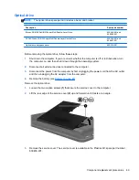
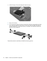
Remove the Phillips PM2.5×6.0 screw that secures the optical drive to the computer.
5.
Insert a thin tool, such as an unbent paper clip
(1)
, into the optical drive release hole. (The
optical drive tray releases.)
6.
Use the optical drive tray to remove the optical drive
(2)
from the computer.
7.
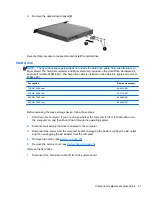
If it is necessary to replace the optical drive bracket, position the optical drive with the rear panel
toward you.
8.
Remove the two Phillips PM2.0×4.0 screws
(1)
that secure the bracket to the optical drive.
50
Chapter 4 Removal and replacement procedures
Содержание Pavilion g4
Страница 1: ...HP G4 Notebook PC Maintenance and Service Guide ...
Страница 4: ...iv Safety warning notice ...
Страница 8: ...viii ...
Страница 23: ...Front Component Description Speakers 2 Produce sound Front 15 ...
Страница 26: ...3 Illustrated parts catalog 18 Chapter 3 Illustrated parts catalog ...
Страница 28: ...Computer major components 20 Chapter 3 Illustrated parts catalog ...
Страница 103: ...Reverse this procedure to reassemble and install the display assembly Component replacement procedures 95 ...
Страница 132: ......

