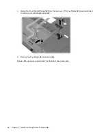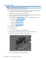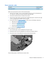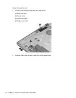
3.
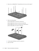
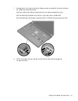
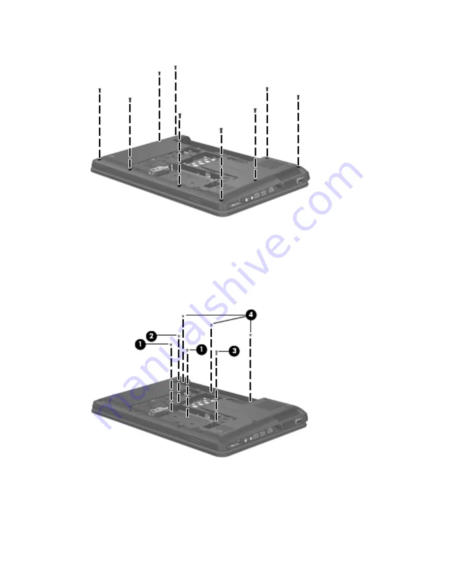
Remove the nine Phillips PM2.5×7.0 screws that secure the top cover to the computer.
4.
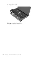
Remove the following screws:
(1)
Two Phillips PM 2.5×4.0 screws in the hard drive bay
(2)
One Philllips PM2.5×6.0 screw near the memory module bay
(3)
One Philllips PM2.5×6.0 screw on the right side of the hard drive bay
(4)
Three Phillips PM2.5×6.0 screws in the battery bay
5.
Turn the computer right-side up, with the front toward you.
6.
Open the computer.
60
Chapter 4 Removal and replacement procedures
Содержание Pavilion g4
Страница 1: ...HP G4 Notebook PC Maintenance and Service Guide ...
Страница 4: ...iv Safety warning notice ...
Страница 8: ...viii ...
Страница 23: ...Front Component Description Speakers 2 Produce sound Front 15 ...
Страница 26: ...3 Illustrated parts catalog 18 Chapter 3 Illustrated parts catalog ...
Страница 28: ...Computer major components 20 Chapter 3 Illustrated parts catalog ...
Страница 103: ...Reverse this procedure to reassemble and install the display assembly Component replacement procedures 95 ...
Страница 132: ......

