176
System Id: 0000.0000.0001
Interface: vlan200 Circuit Id: 0000.0000.0001.01
State: Up HoldTime: 25s Type: L1(L1L2) PRI: 64
System Id: 0000.0000.0001
Interface: vlan200 Circuit Id: 0000.0000.0001.01
State: Up HoldTime: 27s Type: L2(L1L2) PRI: 64
<SwitchB> display isis route
Route information for ISIS(1)
-----------------------------
ISIS(1) IPv4 Level-1 Forwarding Table
-------------------------------------
IPV4 Destination IntCost ExtCost ExitInterface NextHop Flags
--------------------------------------------------------------------------
14.14.14.0/24 10 NULL vlan200 Direct D/L/-
44.44.44.44/32 10 NULL Loop0 Direct D/-/-
12.12.12.0/32 10 NULL vlan200 14.14.14.4 R/L/-
22.22.22.22/32 10 NULL vlan200 14.14.14.4 R/L/-
Flags: D-Direct, R-Added to RM, L-Advertised in LSPs, U-Up/Down Bit Set
ISIS(1) IPv4 Level-2 Forwarding Table
-------------------------------------
IPV4 Destination IntCost ExtCost ExitInterface NextHop Flags
--------------------------------------------------------------------------
14.14.14.0/24 10 NULL vlan200 Direct D/L/-
44.44.44.44/32 10 NULL Loop0 Direct D/-/-
12.12.12.0/32 10 NULL
22.22.22.22/32 10 NULL
Flags: D-Direct, R-Added to RM, L-Advertised in LSPs, U-Up/Down Bit Set
The output shows that the neighbor relationships and routing information on Switch A and Switch
B have not changed. The neighbors cannot sense the switchover on Switch S.
IS-IS FRR configuration example
Network requirements
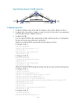
Switch S, Switch A, and Switch D belong to the same IS-IS routing domain as illustrated in
.
Configure IS-IS FRR so that when the link between Switch S and Switch D fails, traffic can be switched to
Link B immediately.


